
Infrared sensor module using rotary ultrasonic motor

Inactive Publication Date: 2016-11-03
ECO DM LAB
View PDF6 Cites 9 Cited by
  • Summary
  • Abstract
  • Description
  • Claims
  • Application Information

AI Technical Summary

Benefits of technology

The present invention provides an infrared sensor module that uses a rotary ultrasonic motor for periodic rotation and continuous detection of signals. The module has a simple integrated structure and allows for detection of infrared rays even from a stationary object. Additionally, the Fresnel lens can be designed to block the entire infrared rays incident on the sensor by rotating due to the motor.

Problems solved by technology

However, because the pyroelectric infrared sensor detects a transitional temperature change, once the pyroelectric material gains stability after a temperature change, further output is not detected.
For this reason, the pyroelectric infrared sensor has a critical problem in terms of applicable areas.
Also, in case manufacturing precision of slits of a slit plate is not high, blocking-level variation is large, cost of manufacturing the slits is high, and manufacturing slits suitable for a piezoelectric bimorph whose end actually executes a circular arc motion rather than a linear motion is difficult.
Further, there is a manufacturing difficulty associated with requiring two piezoelectric bimorphs that have perfectly matched size and piezoelectric characteristics.
Further, because a hole is formed at the top of a shield box within which an infrared ray sensor is installed and air currents are generated due to slit plates installed at the ends of the piezoelectric bimorphs moving left and right, there is a problem of increased noise.
The reason for these problems is an inadequate displacement of a piezoelectric bimorph, and although research is underway for increasing the displacement, structural complexities have caused a difficulty for commercial adaptation.

Method used


Image

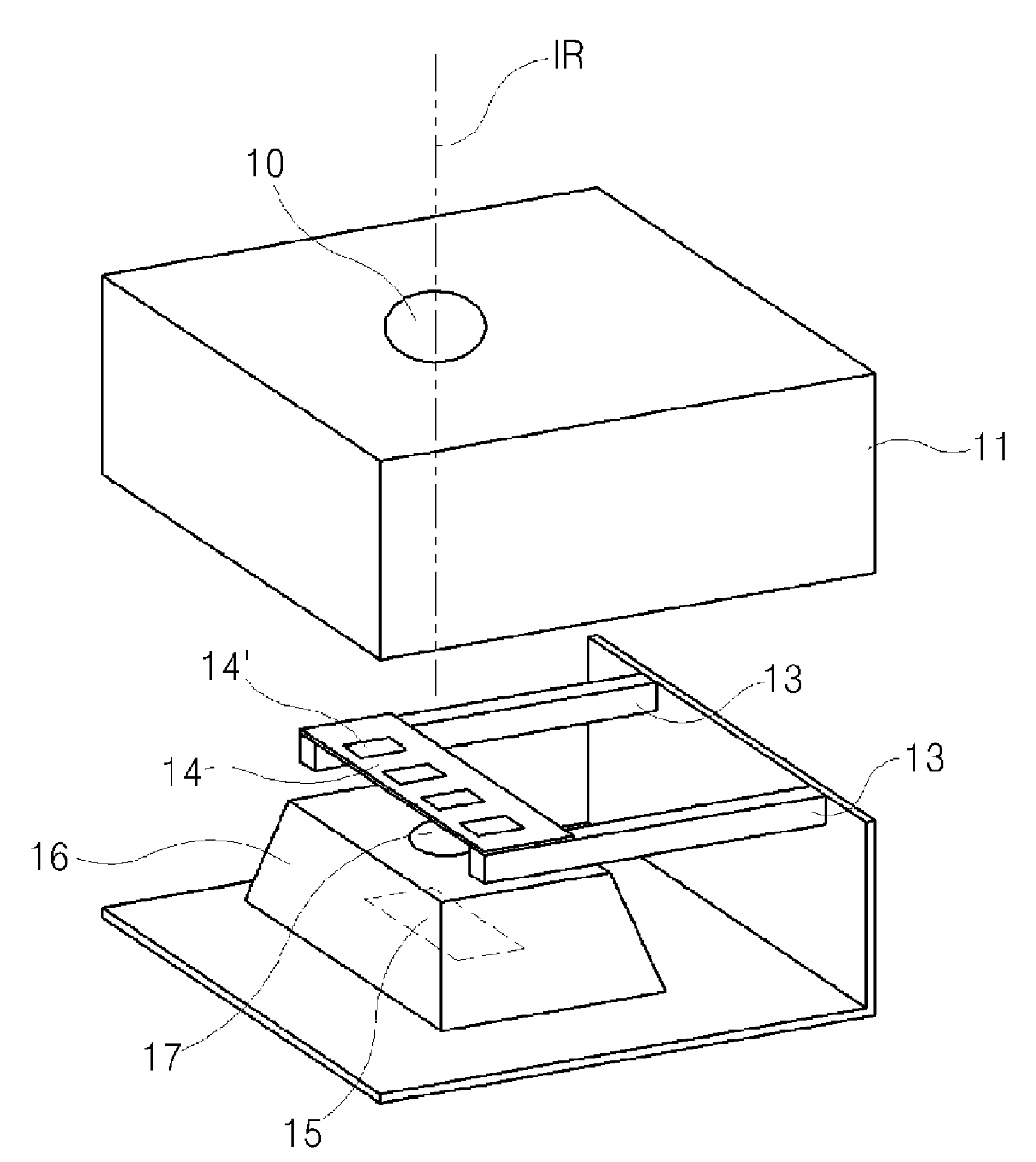
  • Infrared sensor module using rotary ultrasonic motor
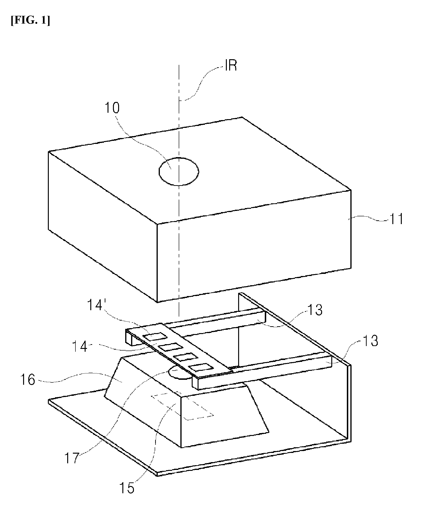
  • Infrared sensor module using rotary ultrasonic motor
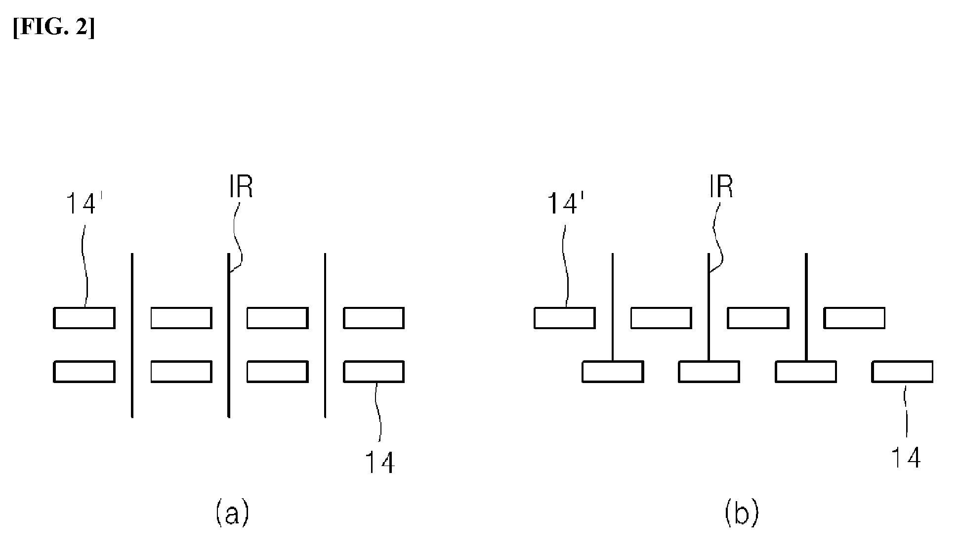
  • Infrared sensor module using rotary ultrasonic motor

Examples


Embodiment Construction

[0037]Hereinafter, an infrared ray sensor module utilizing a rotary ultrasonic motor according to one embodiment of the present invention will be described in detail with reference to accompanying drawings.

[0038]FIG. 3 is configurational diagram for an infrared ray sensor module utilizing a rotary ultrasonic motor according to one embodiment of the present invention, and FIG. 4 is a detailed configurational diagram for an infrared ray sensor module utilizing a rotary ultrasonic motor according to one embodiment of the present invention.

[0039]Referring to FIGS. 3 and 4, an infrared ray sensor module utilizing a rotary ultrasonic motor according to one embodiment of the present invention (hereinafter, simply “infrared ray sensor module”) 100 includes an infrared ray sensor 103, a rotary ultrasonic motor 110, a Fresnel lens 120, an oscillation unit 140, and a control unit 130.

[0040]As is commonly known, the infrared ray sensor 103 is a device that utilizes infrared rays to convert a ph...


PUM


Abstract

An infrared sensor module utilizing a rotary ultrasonic motor is disclosed. The infrared sensor module utilizing a rotary ultrasound motor according to one embodiment of the present invention comprises: an infrared sensor for detecting an object that radiates infrared rays; a rotary ultrasonic motor including a piezoelectric diaphragm having a partitioned electrode structure in a pinwheel shape in a plate body formed with a piezoelectric material and a ring-shaped rotator driven by torsional vibrations generated along the side surfaces of the piezoelectric diaphragm; a Fresnel lens rotatably provided by being coupled to the rotator to control intermittent blocking of the infrared rays incident in the front direction of the infrared sensor; an oscillation unit for outputting a square wave required for the rotary ultrasonic motor; and a control unit for controlling the oscillation unit by using a signal detected by the infrared sensor and controlling the driving of the rotary ultrasonic motor.

Description

CROSS-REFERENCE TO RELATED APPLICATION(S)[0001]This application claims priority from Korean Patent Application No. 10-2013-0154032, filed on Dec. 11, 2013, in the Korean Intellectual Property Office, the disclosure of which is incorporated herein by reference in its entirety.BACKGROUND[0002]1. Field[0003]One embodiment of the present invention relates to an infrared sensor module and, more specifically, to an infrared sensor module utilizing a rotary ultrasonic motor for which periodic rotation is possible utilizing a rotary ultrasonic motor, low voltage driving is possible, and continuous detection of a signal is possible even from a stationary infrared ray radiating object.[0004]2. Description of Related Art[0005]As is well known, a pyroelectric infrared sensor utilizes the pyroelectric characteristic of a pyroelectric material and, based on Blackbody radiation, utilizes a temperature change resulting from absorption of radiated infrared ray energy.[0006]Being capable of detecting...

Claims


Application Information

Patent Timeline
IPC IPC(8): G01J5/02G01J5/00G01J5/08
CPCG01J5/0205G08B13/193G01J5/0025G01J5/0806G01J5/0022G01J1/44
Inventor YOON, MAN-SOON
Owner ECO DM LAB
Learn More