A valve and a method of controlling a valve in a fluid conduit

a technology of fluid conduit and valve valve, which is applied in the direction of valve details, flow control with auxiliary non-electric power, valve arrangement, etc., can solve the problems that the pilot actuator and some of its components (e.g. bottom and upper chambers, discs, membrane rings, etc., may be quite bulky), and achieve simple and reliable mechanical sensing, simplified installation process, and easy maintenance and repair

Active Publication Date: 2016-10-27
IMI HYDRONIC ENG INT SA
View PDF17 Cites 12 Cited by
  • Summary
  • Abstract
  • Description
  • Claims
  • Application Information

AI Technical Summary

Benefits of technology

[0014]The present invention is based on the realization that the difference in pressure over the valve can be used for regulating the volume of a variable volume chamber. In particular, by arranging controllable circuits, the supply of fluid to and from the variable volume chamber can be regulated such that a variable opening degree of the main valve is achieved so that the flow rates can be adjusted in a precise manner. This setup of the variable volume chamber is more or less independent of the size of the valve. Thus, advantages include less wear, less maintenance and a space saving in comparison with today's solution.
[0039]According to an exemplary embodiment, the variable volume chamber is located inside the valve closing member. By arranging the variable volume chamber inside the closing member, the size of the internal chamber inside the valve body is efficiently utilized with less added extra volume to accommodate the variable volume chamber.

Problems solved by technology

Depending on the particular implementation, the pilot actuator and some of its components (e.g. bottom and upper chambers, disc, membrane ring, membrane, safety spring and main axis) may be quite bulky.

Method used


Image

  • A valve and a method of controlling a valve in a fluid conduit
  • A valve and a method of controlling a valve in a fluid conduit
  • A valve and a method of controlling a valve in a fluid conduit

Examples


Embodiment Construction

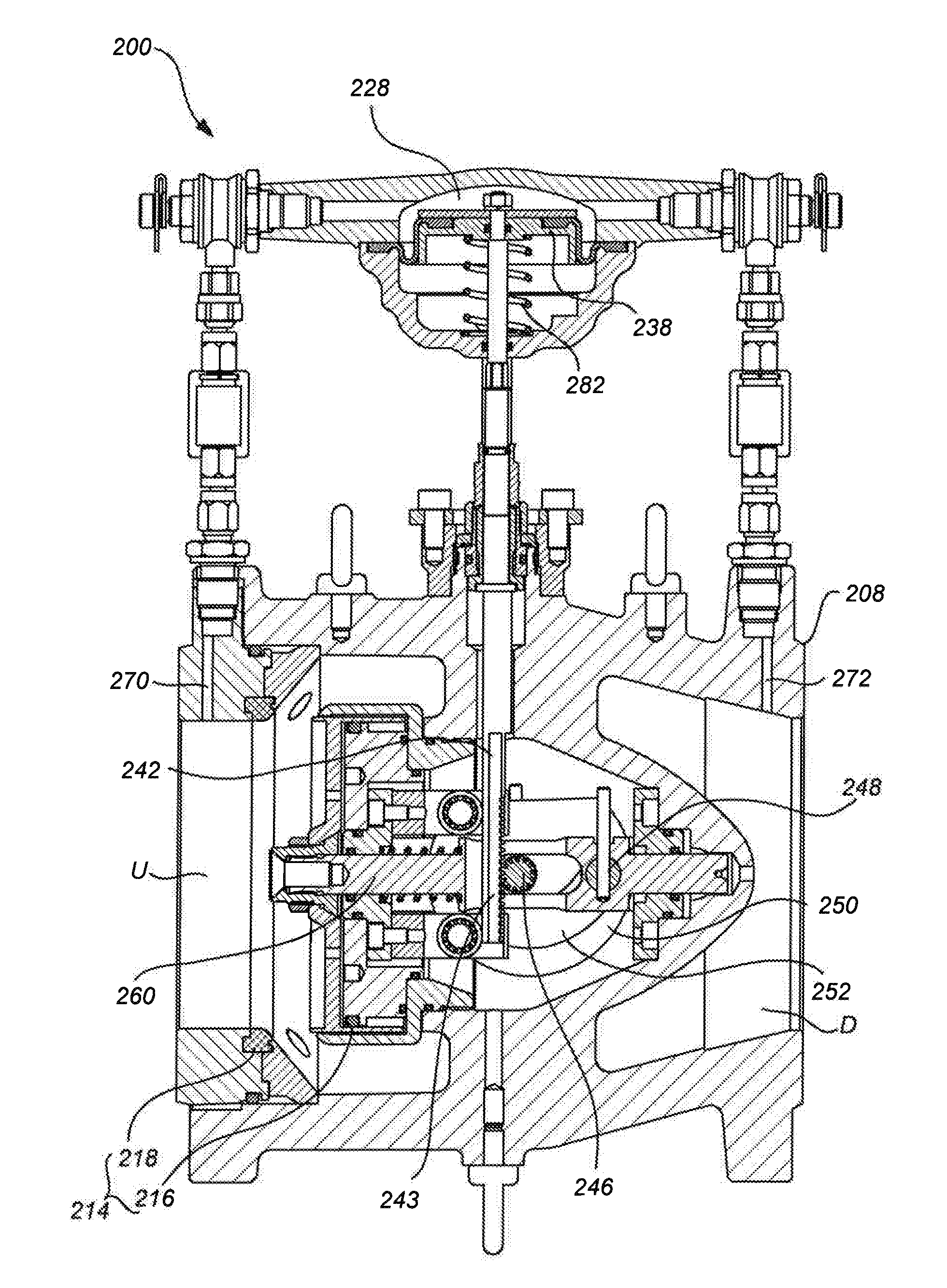
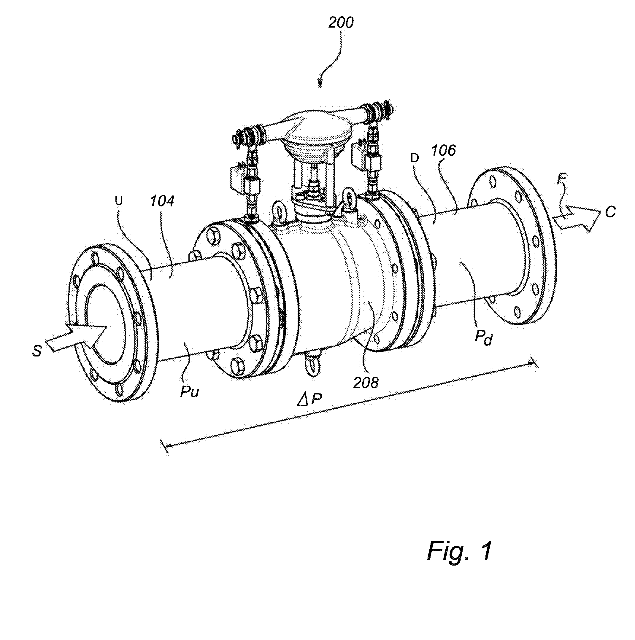
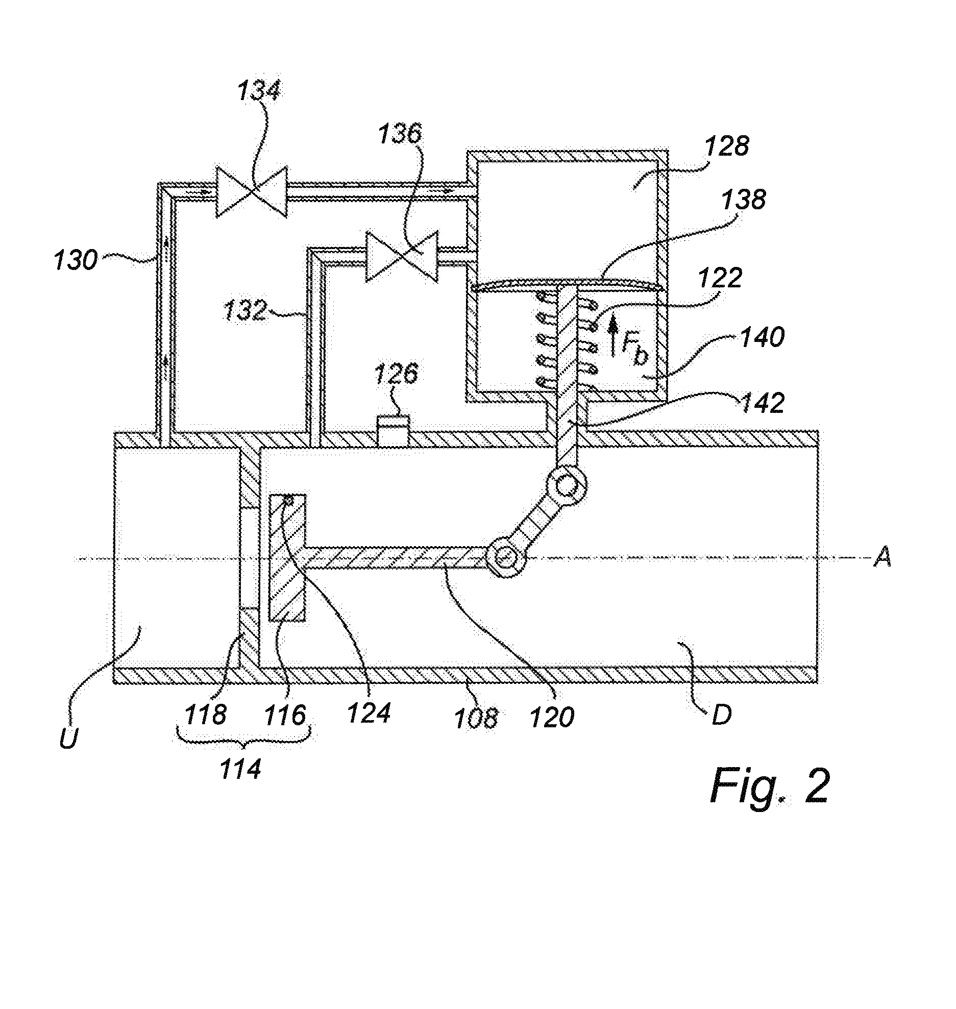
[0061]In the following description, a valve according to exemplary embodiments of the present invention is described in the context of a fluid distribution system. It should be noted that this by no means limits the scope of the present invention, which is equally applicable to other types of industrial applications, such as fluid distribution systems in manufacturing processes (e.g. chemical processes, heating or cooling for process machines, etc.). Additionally, the valve may have a valve body which comprises several fluid inlets and fluid outlets.

[0062]Furthermore, in the following drawings it will be assumed that the exemplified valves of the different embodiments are installed on a supply pipe, wherein the high pressure side is upstream of the valve and the low pressure side is downstream of the valve. However, it should be understood that, although not illustrated in the drawings, valves according to embodiments of the invention could be installed on return pipes, in which cas...


PUM


Abstract

The present invention relates to a valve having a control function and a method for controlling a valve in a fluid conduit in order to adapt flow rates and / or differential pressure rates. The valve comprises a fluid inlet and a fluid outlet and a valve closing member located inside a valve body. The valve closing member is operationally connected to a variable volume chamber, which is adapted to extract energy from the fluid in order to provide either an opening or a closing displacement of the valve closing member such that the degree of opening of the valve can be changed. The supply of fluid to and from the variable volume chambers may be regulated by electronically controlled valves.

Description

FIELD OF THE INVENTION[0001]The present invention relates to a valve for regulating fluid flow and / or pressure in fluid conduits. The fluid conduits can be designed for e.g. heating, cooling, water supply or industrial manufacturing processes. The invention also relates to a method of controlling a valve in a fluid conduit.BACKGROUND ART[0002]Fluid distribution systems are designed to feed a fluid from a source to a consumption point. Each consumption point typically has a calculated and designed optimal flow or differential pressure requirement. However, depending on the type of hydronic system, the flow requirement is often variable over time and can change with factors like seasonality (e.g. summer or winter) and daily weather conditions. Specifically, the seasonality effect can lead to changes in the load at the consumption points, and may be due to factors like temperature changes in the system fluid (e.g. for heating systems), changes in demand for the system fluid (e.g. for d...

Claims


Application Information

Patent Timeline
Patent Type & Authority Applications(United States)
IPC IPC(8): F16K31/124F16K31/126F16K31/163F16K1/12F16K31/54
CPCF16K31/1245F16K1/12F16K31/1262F16K31/163F16K31/1266F16K31/54G05D7/005F16K1/34
Inventor THYBO, CLAUSLAH, SLAVKOBOZIC, GREGORVOLOVEC, PETER
Owner IMI HYDRONIC ENG INT SA
Why Eureka
Try Eureka