
Switching device and operating procedure therefor

a technology of switching device and operating procedure, which is applied in the direction of data switching network, digital transmission, bus network, etc., can solve the problem of excessive data volum

Active Publication Date: 2016-10-13
ROBERT BOSCH GMBH
View PDF5 Cites 8 Cited by
  • Summary
  • Abstract
  • Description
  • Claims
  • Application Information

AI Technical Summary

Benefits of technology

This patent describes a control device and a switch that can improve the function and safety of a network system, such as in a motor vehicle. The control device can be used to control the switching device, which allows communication between different physical interface units. The switch can be designed as an Ethernet switch, and the system can be operated in a cost-effective way to increase redundancy and improve safety in a fault condition. The switch and control device can be situated on a shared circuit board, which simplifies design and reduces cost. The patent also introduces a backbone for an Ethernet network system for a motor vehicle, which allows for a simple and reliable operation.

Problems solved by technology

The faulty state may be caused, for example, by a defective electronic component or an undervoltage or an overvoltage in a motor vehicle electrical system, or by electromagnetic radiation or a program error, or by a possibly excessively high data volume (memory fault, “buffer overflow”).

Method used


Image

  • Switching device and operating procedure therefor
  • Switching device and operating procedure therefor
  • Switching device and operating procedure therefor

Examples


Embodiment Construction

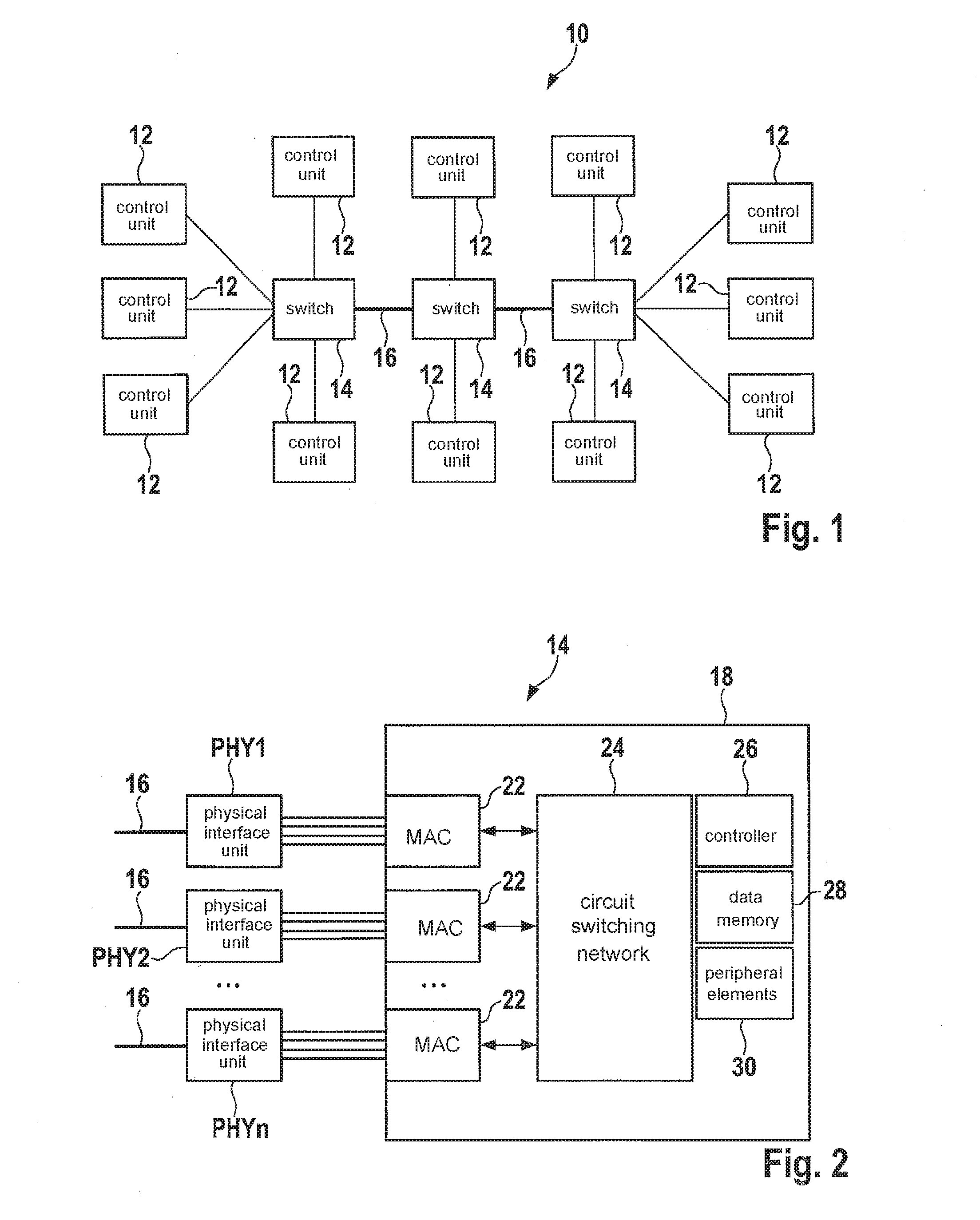
[0040]FIG. 1 shows a simplified diagram for an Ethernet network system 10 for a motor vehicle which is not shown. In the present example, Ethernet network system 10 includes multiple Ethernet-capable control units 12 and in the present example three switching units, which in the present example are each designed as a so-called switch 14 (“Ethernet switch”). Switches 14 are connected to each other via a backbone 16 of network system 10. A subset of control units 12 is connected in each case to switches 14.

[0041]Switches 14 are generally connected to backbone 16 with the aid of physical interface units (see FIGS. 2 through 7). A respective media-independent interface of the physical interface unit is contacted with an “internal” area of respective switch 14, for example, and a respective media-[in]dependent interface of the physical interface unit is contacted with a line (for example a cable or a glass fiber) of backbone 16.

[0042]If, for example, central switch 14 shown in FIG. 1 is ...


PUM


Abstract

A switching device including a first interface for contacting a media-independent interface of a first physical interface unit, and a second interface for contacting a media-independent interface of a second physical interface unit. The switching device is designed to couple the first interface to the second interface.

Description

CROSS REFERENCE[0001]The present application claims the benefit under 35 U.S.C. §119 of German Patent Application No. 102015206483.2 filed on Apr. 10, 2015, which is expressly incorporated herein by reference in its entirety.BACKGROUND INFORMATION[0002]The present invention relates to a switching device, a switch, a control and / or regulating device, a network system and an operating procedure for a switching device.[0003]Arrangements of electronic assemblies, such as control units, in motor vehicles which are able to communicate with each other with the aid of different bus systems and / or protocols are known from the market. For example, a motor vehicle may include up to approximately 100 such control units or assemblies.SUMMARY[0004]Features which may be important for the present invention are described below and are shown in the figures. The features may be important for the present invention either alone or also in various combinations, without making explicit reference thereto a...

Claims


Application Information

Patent Timeline
IPC IPC(8): H04L12/40H04L12/933
CPCH04L12/40013H04L49/102H04L2012/445H04L2012/40273H04L2012/40215H04L12/40182
Inventor ZINNER, HELGE
Owner ROBERT BOSCH GMBH
Learn More