Cylindrical superconducting magnet

a superconducting magnet and cylindrical technology, applied in the direction of superconducting magnets/coils, measurement devices, instruments, etc., can solve the problems of spreading the dissipation of stored energy, single parts of the coil assembly becoming so hot that they are damaged, etc., to avoid or reduce the generation of thermal stress, remove or reduce the thermal mismatch

Inactive Publication Date: 2016-09-22
SIEMENS PLC
View PDF0 Cites 0 Cited by
  • Summary
  • Abstract
  • Description
  • Claims
  • Application Information

AI Technical Summary

Benefits of technology

[0008]The present invention provides a cylindrical superconducting magnet structure in which annular spacers are provided, yet the problems of differential thermal expansion and contraction are reduced or eliminated. The present invention removes or reduces the thermal mismatch between materials used for the coils and the spacers, and so avoids or reduced generation of thermal stress at interfaces between coils and spacers.

Problems solved by technology

If one part of one coil quenches, the resultant heating rapidly causes the adjacent coils to quench, spreading the dissipation of stored energy and ensuring that no single part of the coil assembly becomes so hot that it is damaged.

Method used


Image

  • Cylindrical superconducting magnet
  • Cylindrical superconducting magnet
  • Cylindrical superconducting magnet

Examples


Embodiment Construction

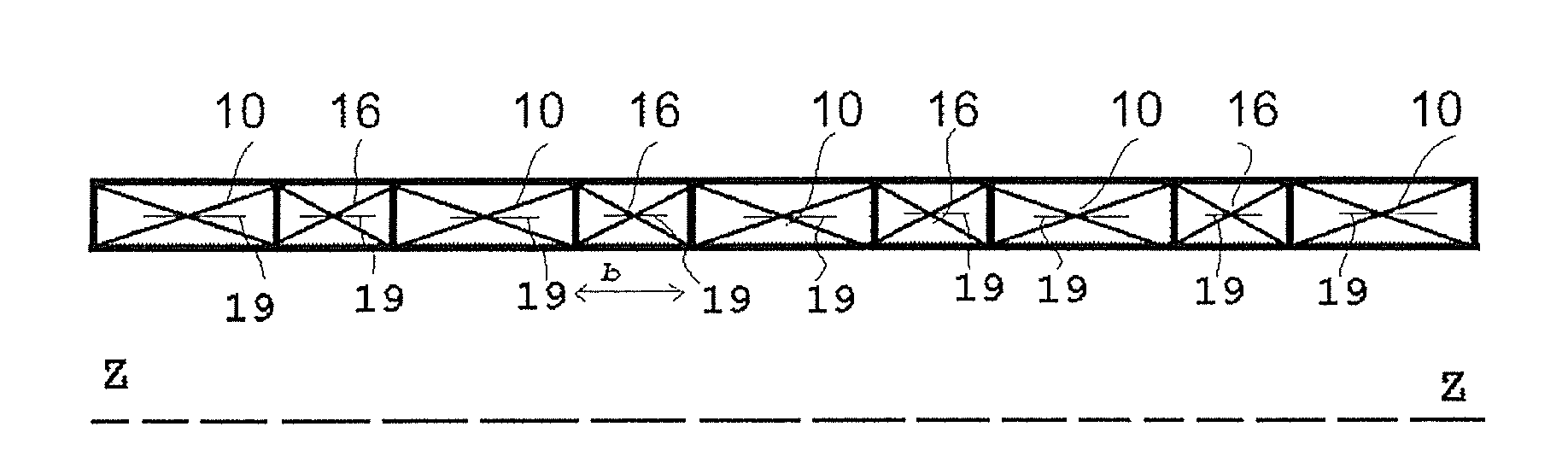
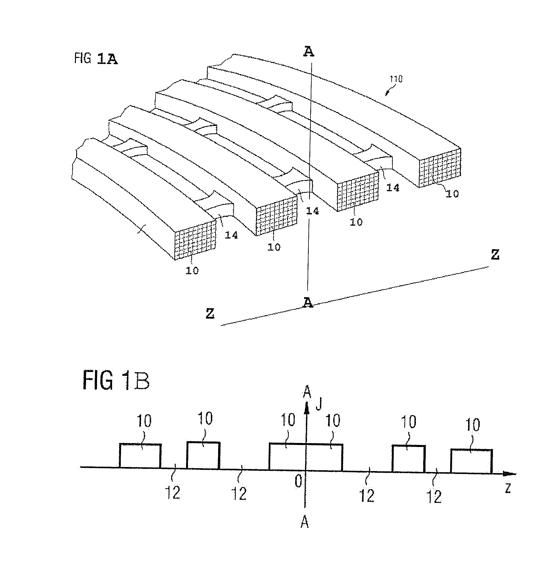
[0020]According to the present invention, the discrete, circumferentially-spaced spacers 14 of known coil structures of FIG. 1A described above are replaced by turns of wire, typically impregnated with resin, and having very similar thermal properties to those of the magnet coils 10. These turns of wire make up coils which are bonded axially between superconducting coils of the magnet structure. For ease of reference in the following description, these turns of wire will be referred to as “spacer coils”, and the magnet coils 10 will be referred to as “main coils”.

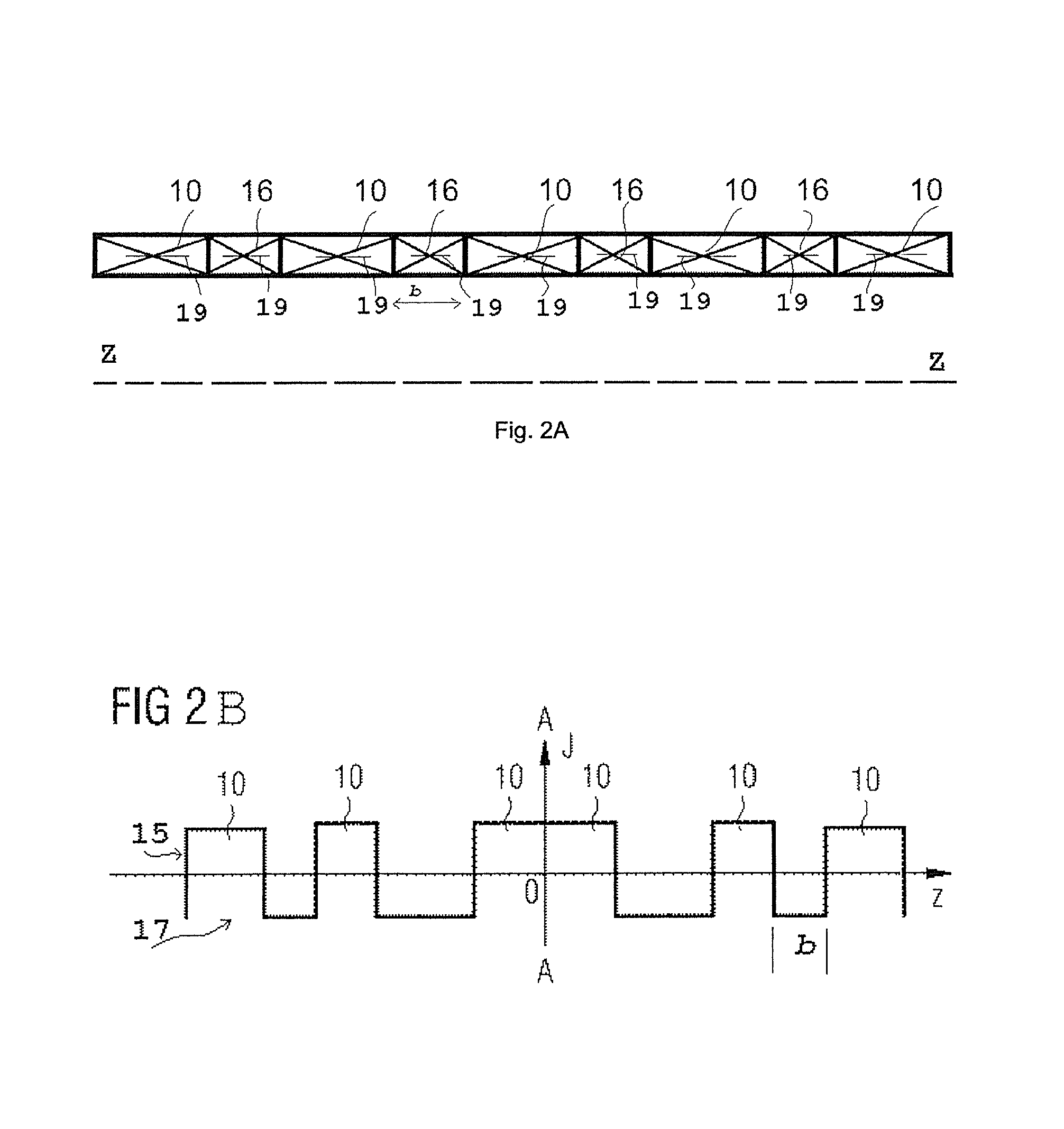
[0021]FIG. 2A illustrates an axial half-cross-section of a monolithic superconducting magnet structure according to an embodiment of the present invention. Five main coils 10 are represented. Between the main coils 10 are spacer coils 16. The illustration in FIG. 2A is schematic only. Spacer coils 16 would be expected to have a smaller axial dimension b than the main coils 10.

[0022]Preferably, the spacer coils 16 have inner...


PUM

PropertyMeasurementUnit
magnetic fieldaaaaaaaaaa
superconductingaaaaaaaaaa
current densityaaaaaaaaaa

Abstract

A cylindrical superconducting magnet structure (24) comprising two superconducting main coils (10) respectively axially spaced apart by a spacer coil (16), said main coils and said spacer coil being bonded together in a single self-supporting structure.

Description

BACKGROUND OF THE INVENTION[0001]1. Field of the Invention[0002]The present invention relates to cylindrical superconducting magnet structures, particularly such structures in which a number of separate superconducting coils are provided, linked by spacers, but which are formed into a single self-supporting structure. Examples of such structures are described in International patent application WO2011 / 148163.[0003]2. Description of the Prior Art[0004]FIG. 1A illustrates a conventional monolithic cylindrical coil structure 110 of the general type described above. A-A represents an axial mid-plane, and Z-Z represents an axial direction. Four coils 10 are provided and are retained in defined relative positions by spacers 14. In the illustrated example, discrete spacers 14 are placed at circumferential intervals around the circumference of the coils, as illustrated, and each spacer 14 is bonded at its axial extremities to axial extremities of two adjacent coils 10. The spacers 14 may be...

Claims


Application Information

Patent Timeline
Patent Type & Authority Applications(United States)
IPC IPC(8): H01F6/06H01F6/02
CPCH01F6/02H01F6/065G01R33/3815H01F6/06G01R33/3802H01F5/02H01F41/048
Inventor HUTTON, GRAHAM
Owner SIEMENS PLC
Why Eureka
Try Eureka