
Counting bar-shaped products based upon acquired images

a technology of acquired images and counting devices, applied in the direction of counting objects on conveyors, instruments, television systems, etc., can solve the problems of unreliable, slow and unreliable mechanical counting devices, and the effect of reducing the number of objects

Active Publication Date: 2016-09-15
PRIMETALS TECH GERMANY
View PDF3 Cites 2 Cited by
  • Summary
  • Abstract
  • Description
  • Claims
  • Application Information

AI Technical Summary

Benefits of technology

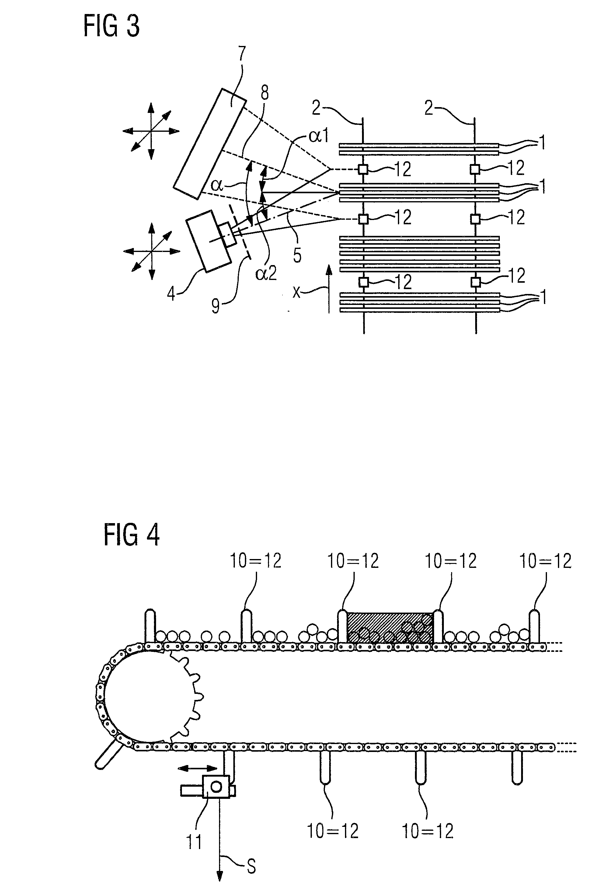
The present invention allows for reliable and accurate count of products with minimal mechanical changes to existing equipment. By triggering the acquisition of images and processing them in a reliable way, the invention has achieved the ability to determine conveyed bar-shaped products. The camera is positioned in a way that minimizes the angle between the optical axis of the camera and the product's longitudinal direction, reducing the likelihood of blocking the front end of one product with another. The front ends of the products in the conveyor section are illuminated, improving image contrast and detection reliability.

Problems solved by technology

Mechanical counting devices are relatively slow and unreliable.
Furthermore, they are subject to wear.

Method used


Image

  • Counting bar-shaped products based upon acquired images
  • Counting bar-shaped products based upon acquired images
  • Counting bar-shaped products based upon acquired images

Examples


Embodiment Construction

[0046]As shown in FIG. 1, bar-shaped products 1 shall be conveyed by a conveyor device. The bar-shaped products 1 extend in a longitudinal direction x over a length 1. The longitudinal direction x usually is horizontal. The length 1 usually is in the range of several metres, for example between 3 m and 15 m, especially between 4 m and 12 m. The bar-shaped products 1 often have a circular cross-section with a diameter of at least 8 mm and up to 120 mm. The products 1 may, however, have a non-circular cross-section, for example a square, angle or hexagonal cross-section.

[0047]For conveying the products 1, the conveyor device comprises a conveyor element 2. The conveyor element 2 may be, for example, as shown in FIG. 2, an endless circulating chain. The conveyor element 2 conveys the products 1 in a conveying direction y. The conveying direction y is orthogonal to the longitudinal direction x. Usually it is horizontal.

[0048]As shown in FIG. 1, the conveyor device further comprises a tr...


PUM


Abstract

A conveyor element (2) of a conveyor device conveys bar-shaped products (1) orthogonal to a longitudinal direction (x) of the bar-shaped products (1) oriented in a conveying direction (y). A trigger device (3) provides a trigger signal (S) each time the conveyor element (2) has traveled a predetermined interval. Based upon the respective trigger signal (S), an image (B) is acquired by a camera (4). The image (B) shows front ends of the products (1) in a respective section of the conveyor element (2) corresponding at least to the predetermined interval. Based upon the acquired images (B), the number of bar-shaped products (1) conveyed by the conveyor element (2) is determined.

Description

TECHNICAL FIELD OF THE INVENTION[0001]The present invention concerns a method of operation for a conveyor device for conveying bar-shaped products,[0002]wherein the bar-shaped products are conveyed by a conveyor element in a conveying direction orthogonal to a longitudinal direction of the bar-shaped products.[0003]The present invention further concerns a conveyor device for conveying bar-shaped products,[0004]wherein the conveyor device comprises a conveyor element conveying the bar-shaped products in a conveying direction orthogonal to a longitudinal direction of the bar-shaped products.BACKGROUND OF THE INVENTION[0005]Such a method of operation and the corresponding conveyor device are known to the person skilled in the art.[0006]After rolling of bar-shaped products, the products are cooled down on a cooling bed of a rolling mill. Afterwards, groups of products are strapped into bundles. The bundles are then sent to storage or directly to a customer. It is important to know the n...

Claims


Application Information

Patent Timeline
Patent Type & Authority Applications(United States)
IPC IPC(8): G06M7/04H04N5/225H04N7/18
CPCG06M7/04H04N5/2253H04N5/2252H04N7/183G06M1/101G06M7/00H04N23/51H04N23/54
Inventor KIRKWOOD AZMAT, RUTHCECCARINI, CHRISTOPHERMANORIA, RITESH
Owner PRIMETALS TECH GERMANY
Learn More