
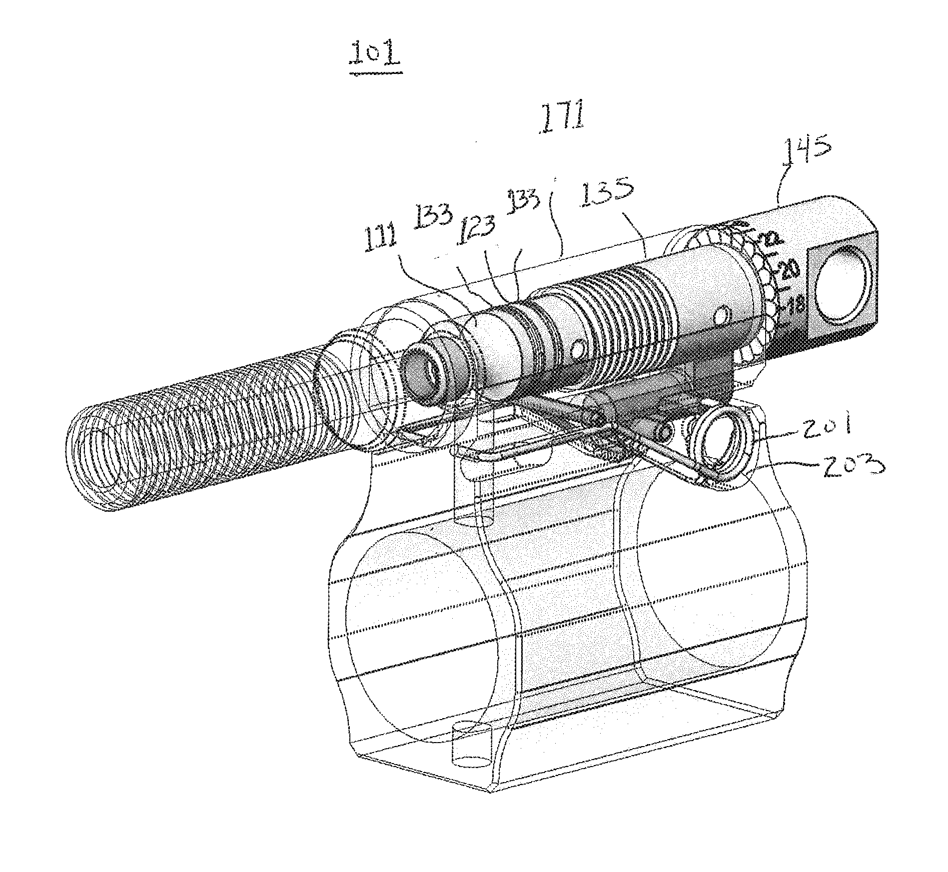
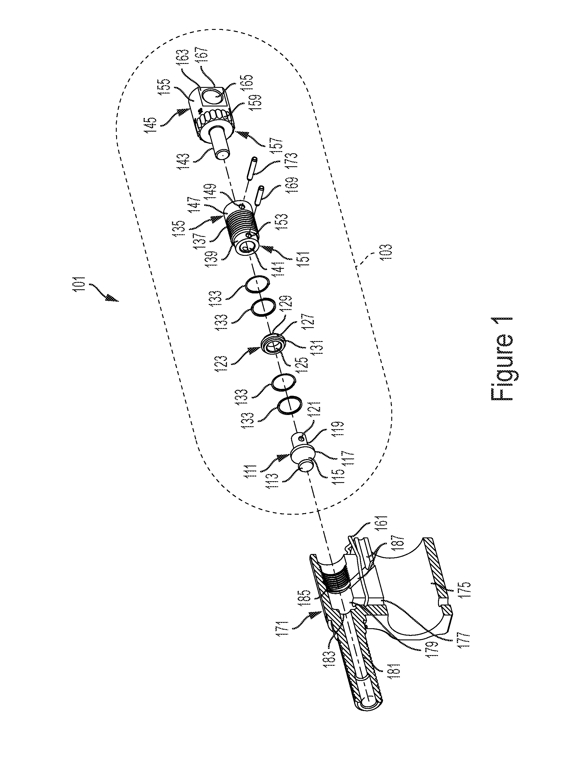
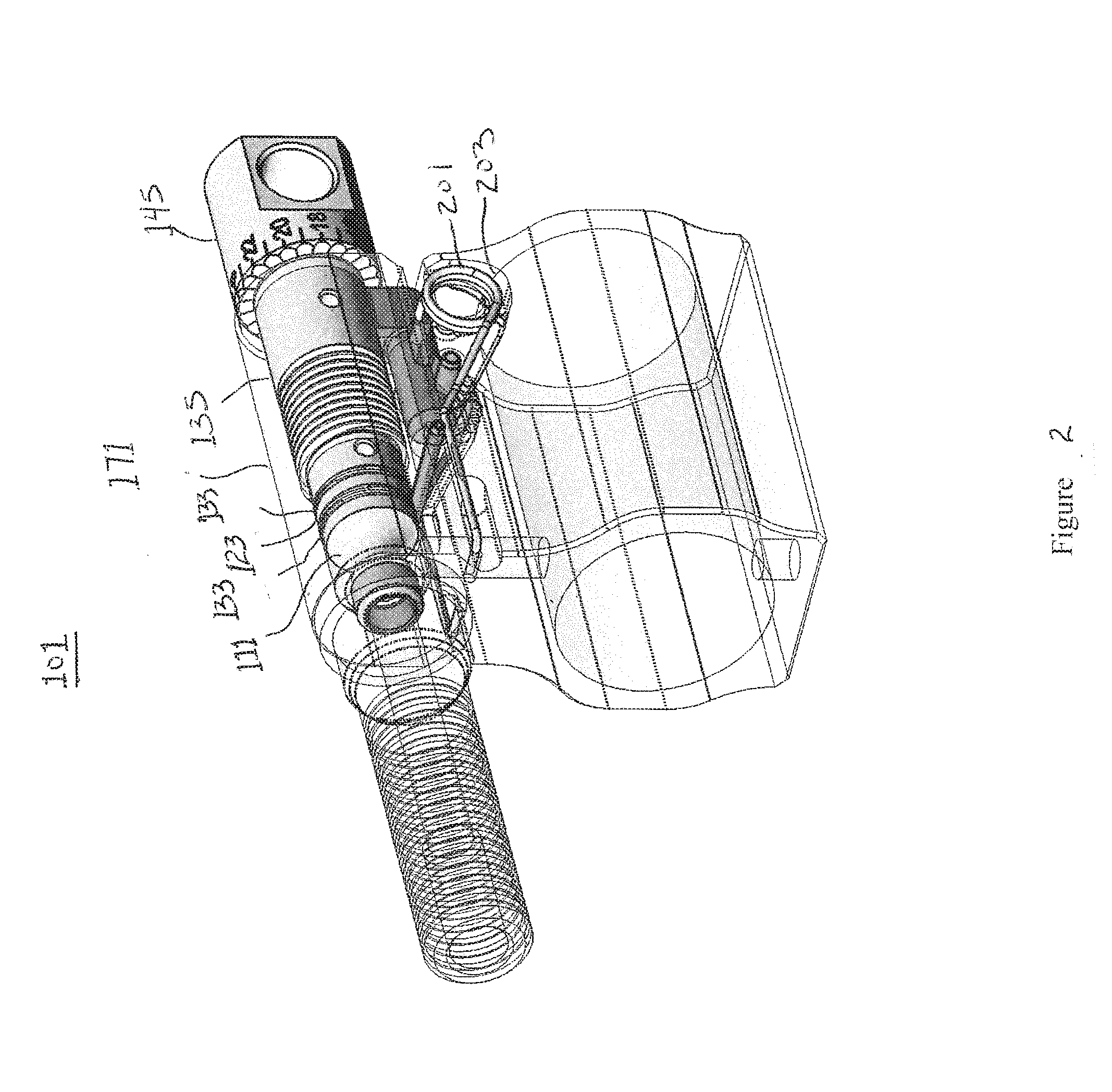
Adjustable gas block

a gas block and adjustable technology, applied in the direction of weapons, weapon components, etc., can solve the problems of premature malfunction, no user's way, and difficulty in choosing a gas port size universally working under all conditions

Active Publication Date: 2016-09-15
LWRC INTERNATIONAL
View PDF8 Cites 17 Cited by
  • Summary
  • Abstract
  • Description
  • Claims
  • Application Information

AI Technical Summary

Benefits of technology

The present invention relates to systems and methods for gas blocks for self-loading firearms. These systems and methods allow for user adjustment of gas flow from a barrel into an operating system, which can be useful for various purposes such as adjusting for different ammunition parameters, suppressors of differing back pressures, changes in rifle conditions, and so on. The systems and methods may include an adjustable gas block with a valve built into it that can be opened or closed to adjust gas flow. The technical effects of the invention include improved gas flow control, user adjustability of gas flow, and reduced noise and flash from firearms.

Problems solved by technology

Unfortunately due to varying lengths of barrels, ammunition variance, and other factors it is very difficult to choose a gas port size which universally works under all conditions.
Further, adjustment of the gas system typically requires a special tool and offers no way for the user to index the system and make adjustments due to mitigating circumstances quickly.
This extra gas, or back pressure increases the firing rate of a weapon during its full auto function, fouls the weapon leading to premature malfunction and to a variety of feeding and extraction problems.
Problems with existing systems may occur due to variations in cartridge, such as different weights, different powder charges, different bullet jackets, etc., friction in the operating system that may change during the life of the rifle, buffer sprint set changes, and suppressors of different back-pressures.
Existing systems may not allow for the rifle operator to compensate for these potential problems.

Method used


Image

  • Adjustable gas block
  • Adjustable gas block
  • Adjustable gas block

Examples


Embodiment Construction

[0016]Systems and methods are described for gas blocks for self-loading firearms to facilitate user adjustment of gas flow from a barrel into an operating system. In particular, the systems and methods may be used for any purpose where adjustable gas blocks may be needed.

[0017]The systems and methods described herein may describe an adjustable gas block for gas piston operated rifles, both semi-automatic and automatic, with or without suppressors. A shooter may be able to adjust for varying ammunition parameters, suppressors of differing back pressures, changes in rifle conditions, such as an increase or decrease of bolt carrier / buffer system frictions, buffer spring set, and spent cartridge ejection angle.

[0018]In certain embodiments, the rifle operator may adjust the gas block via a multi-stepped opening or closing of a valve built into the gas block via an actuator. The number of steps per revolution of the actuator may vary from two or more steps to a continuous adjustment witho...


PUM


Abstract

Systems and methods for an adjustable gas block are described. Systems may include an adjustment subassembly. The adjustment subassembly may include a valve stem end with a front-most portion larger in diameter than the rear-most portion and a boss extending from the forward portion of the valve stem end; a valve ring surrounding the boss of the valve stem end; a valve threaded portion for receiving the boss of the valve stem end and having a threaded portion; and a valve rotator coupled to the valve threaded portion for adjusting the flow of gas. Systems may include a gas block assembly. The gas block assembly may include a gas block through hole; a first duct to direct pressurized gas from a barrel to a plenum; a second duct to direct a regulated volume of gas to a gas operating system; a seat valve to control the regulated volume of gas to the gas operating system; and a gas block threaded portion for coupling to the valve threaded portion. The adjustment subassembly may be coupled to the gas block assembly.

Description

FIELD OF THE INVENTION[0001]The present invention relates to systems and methods for self-loading firearms, and more specifically, to systems and methods for gas blocks for self-loading firearms to facilitate user adjustment of gas flow from a barrel into an operating system.BACKGROUND OF THE INVENTION[0002]The need to regulate the gas flow between the barrel and operating system of a firearm has been a concern since the introduction of auto-loading firearms. Gas is generated during the combustion of gun powder present in the cartridges used in modern firearms. This gas expands violently to push the bullet out of the firearm's barrel. These expanding gases are utilized as a means to operate the action of the host firearm. In modern firearms the preferred method of facilitating the function of an auto-loading weapon is as follows. A hole is placed through the barrel, generally on the top. Location of this hole or gas port varies between operating systems. Generally a gas port size is...

Claims


Application Information

Patent Timeline
IPC IPC(8): F41A5/28
CPCF41A5/28
Inventor SCHILLING, ROBERT S.MILLER, JASON LEELLEWELLYN, MICHAEL R.
Owner LWRC INTERNATIONAL
Learn More