
Dual scrubber vehicle treatment brush assembly

Active Publication Date: 2016-09-15
PISTON OPW INC
View PDF5 Cites 10 Cited by
  • Summary
  • Abstract
  • Description
  • Claims
  • Application Information

AI Technical Summary

Benefits of technology

The present invention provides a rotary brush assembly for a vehicle wash system that improves the cleaning of a vehicle's exterior surface. It also effectively removes drift from hard to clean surfaces, such as wheels and rocker panels, while reducing the number of components required in the system.

Problems solved by technology

However, the high pressure water is generally emitted from a location disposed away from a vehicle and thus is not completely effective in removing dirt from the vehicle exterior.
This generally creates an increased slapping noise due to an increased force of contact between the media elements and the vehicle exterior, which can make the car wash experience unenjoyable for a user.
Also, as the speed of the brush increases, the perception of potential damage to the vehicle exterior increases.
As such, as the rotary hub is driven, the media elements typically only contact the vehicle exterior in a single direction, which limits the cleaning capabilities of the media elements and thus the effectiveness of the wash process.
These rotary brushes are known to have limitations in removing dirt from angled, curved or complex vehicle surfaces, such as wheels or rocker panels.
However, these brushes employ hard or rigid media elements, such as synthetic bristles.
As the bristles can mar a painted surface, they are not suitable for cleaning or treating a vehicle exterior.
Thus, if the media elements secured to these rigid structures encounter angled or curved exterior vehicle surfaces, the brush assemblies cannot accommodate these variations and thus are not suitable for use for cleaning a vehicle exterior for this additional reason.

Method used


Image

  • Dual scrubber vehicle treatment brush assembly
  • Dual scrubber vehicle treatment brush assembly
  • Dual scrubber vehicle treatment brush assembly

Examples


Embodiment Construction

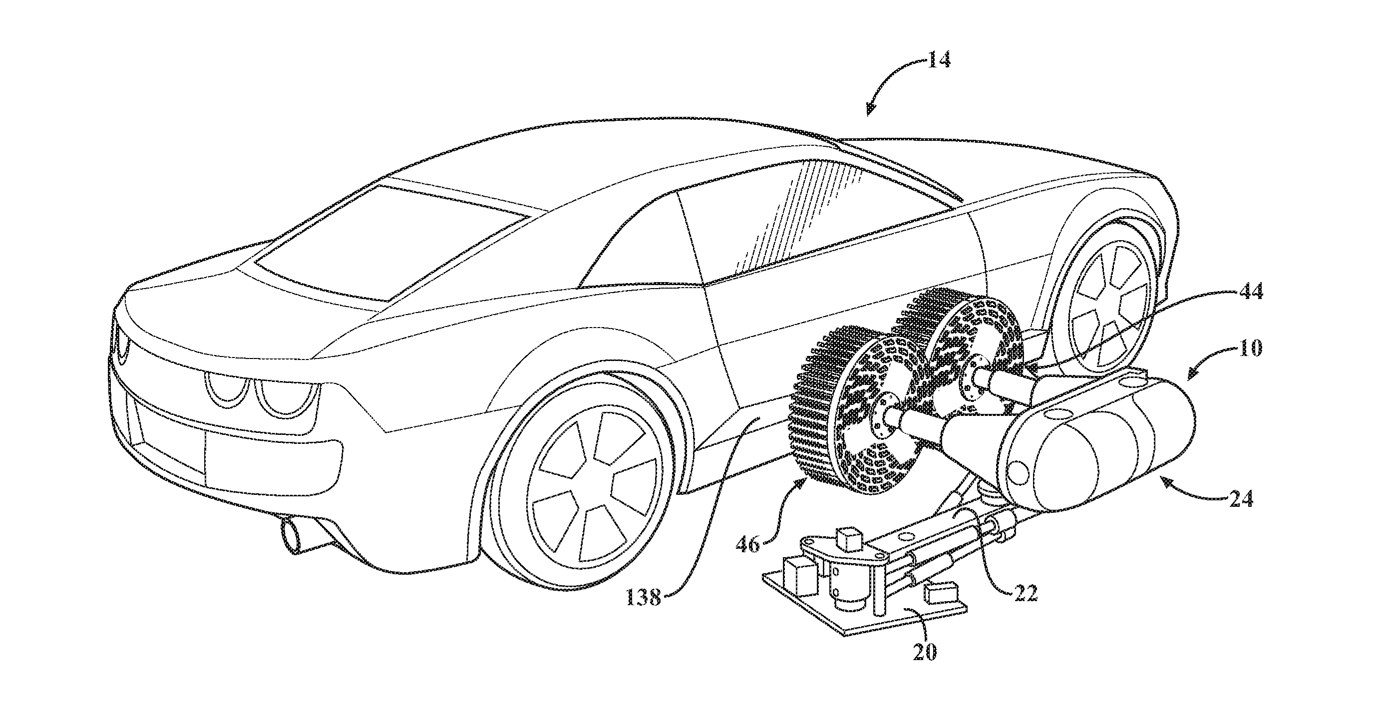
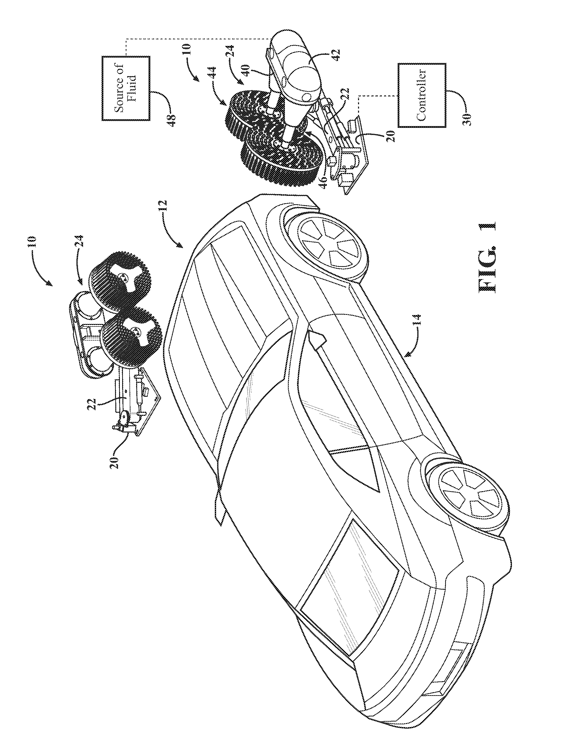
[0028]Referring to the FIGS. which illustrate a vehicle treatment brush assembly 10 according to an aspect of the present disclosure. The vehicle treatment brush assembly 10 may be utilized as part of a vehicle wash system. The vehicle wash system may be configured as a tunnel car wash, where a vehicle is conveyed through the wash process by a conveyor or the like as is known in the art. Alternatively, the vehicle wash system may be configured as a roll-over type where the vehicle remains stationary and the various treatment components are translated and moved with respect to the vehicle to perform the vehicle wash process. Other suitable wash processes and systems may also be employed as are known. It will be appreciated that the disclosed treatment brush assembly could also be employed in connection with a variety of other applications outside of a vehicle wash system, such as a manual or self-serve wash process or in applications unrelated to the wash industry.

[0029]According to ...


PUM


Abstract

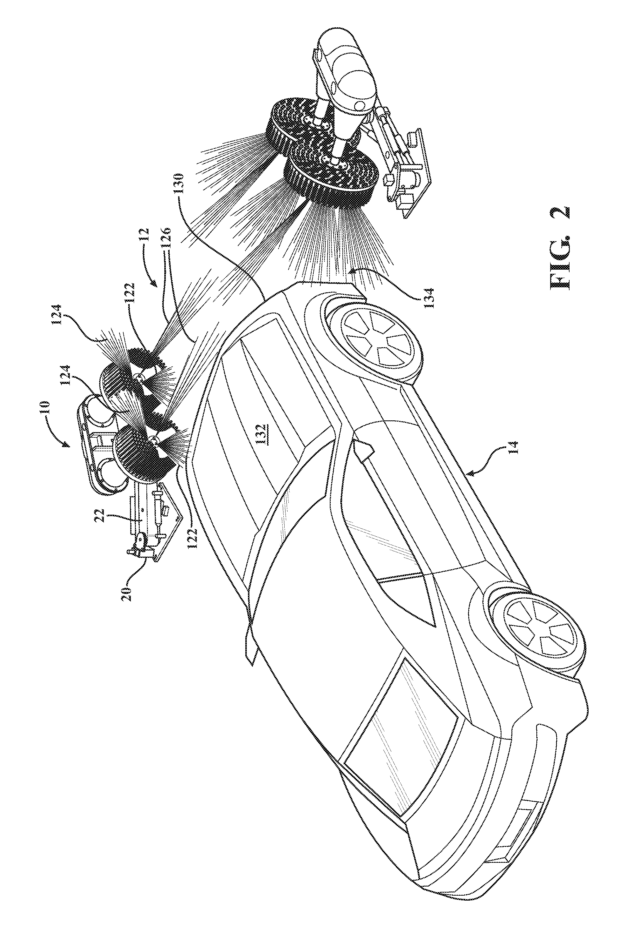
A rotary brush assembly for use in a vehicle wash system, including a base portion, a linkage portion in rotational communication with the base portion and a treatment portion moveable between a first position extended into the vehicle treatment area for engagement with an exterior of a vehicle and a second position retracted from a vehicle treatment area. The treatment portion includes a brush assembly configured to rotate about an axis of rotation. The brush assembly has a backing member, a plurality of media elements secured to the backing member, and a plurality of spray nozzles encapsulated within the plurality of media elements. A plurality of pockets formed on the brush assembly where none of the first plurality of media elements are disposed. The plurality of spray nozzles being disposed at an angle to direct separate streams of high pressure fluid away from the axis of rotation and through the area of the pockets such that the separate streams are substantially not obstructed by any of the plurality of media elements.

Description

CROSS-REFERENCE TO RELATED APPLICATIONS[0001]The present application is a continuation-in-part of U.S. patent application Ser. No. 14 / 691,686, filed Apr. 21, 2015 and entitled “Vehicle Wash Component with Torque Reactor”, which is a continuation-in-part of U.S. patent application Ser. No. 14 / 327,744, filed Jul. 10, 2014 and entitled “Pad Element For A Rotary Brush Vehicle Wash Component”, which claims priority to U.S. Provisional Patent Application Ser. No. 61 / 972,764, entitled “Rotary Brush Apparatus for a Vehicle Wash System”, filed on Mar. 31, 2014 and U.S. Provisional Patent Application Ser. No. 61 / 972,854, entitled “Rotary Brush Apparatus”, filed on Mar. 31, 2014, the disclosures of which are all hereby incorporated by reference.TECHNICAL FIELD[0002]The present disclosure relates generally to a vehicle treatment apparatus for treating an exterior surface of a vehicle. More specifically, the present disclosure relates to a rotary brush assembly for treating an exterior surface o...

Claims


Application Information

Patent Timeline
IPC IPC(8): B60S3/06A46B13/00A46B13/04
CPCB60S3/066A46B2200/3046A46B13/001A46B13/04A46B13/008B60S3/042B60S3/06
Inventor BELANGER, MICHAEL J.KOTRYCH, JERRY A.TOGNETTI, DAVID
Owner PISTON OPW INC
Learn More