
Wireless ECG sensor system and method

a sensor system and wireless technology, applied in the field of wireless electrodes, can solve the problems of limiting patient mobility, requiring electrode suspension, discomfort and unease of patients, etc., and achieve the effect of reliable signal monitoring and improved data collection ability

Active Publication Date: 2016-09-15
MEDICOMP
View PDF2 Cites 42 Cited by
  • Summary
  • Abstract
  • Description
  • Claims
  • Application Information

AI Technical Summary

Benefits of technology

The patent describes a wireless electrode system and method that can better monitor signals and collect data. This can lead to more reliable data collection.

Problems solved by technology

The use of wired connections means that the electrode may become unplugged due to patient or other movement.
Also, having wired connections tethers a patient to a particular piece of machinery, limiting patient mobility or requiring suspending detection using the electrodes if the patient is moved away from the receiving device.
This can be an issue when transporting the patient, particularly in transition between an ambulance and a healthcare facility, or indeed within a healthcare facility.
There is also an issue with patient compliance wearing wired electrodes, as this causes discomfort and unease to the patient.
A lack of compliance with electrode monitoring (e.g., disconnecting the wire from the electrode by the patient) means a break in monitoring and possible error or alert messages being sent to the medical staff.

Method used


Image

  • Wireless ECG sensor system and method
  • Wireless ECG sensor system and method
  • Wireless ECG sensor system and method

Examples


Embodiment Construction

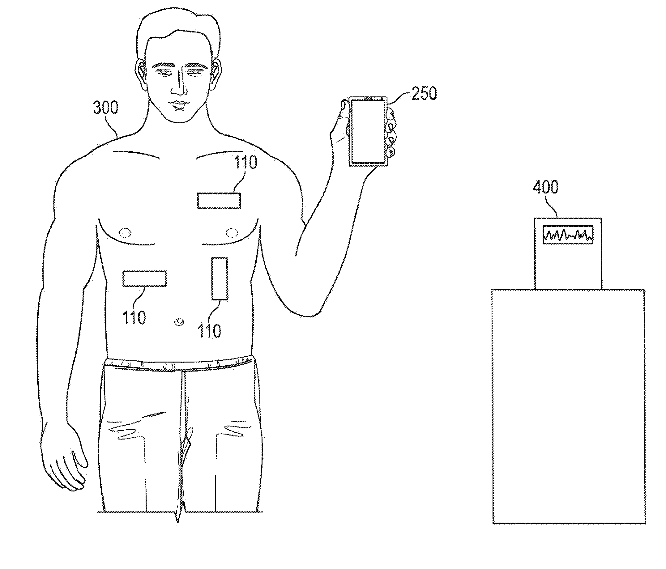
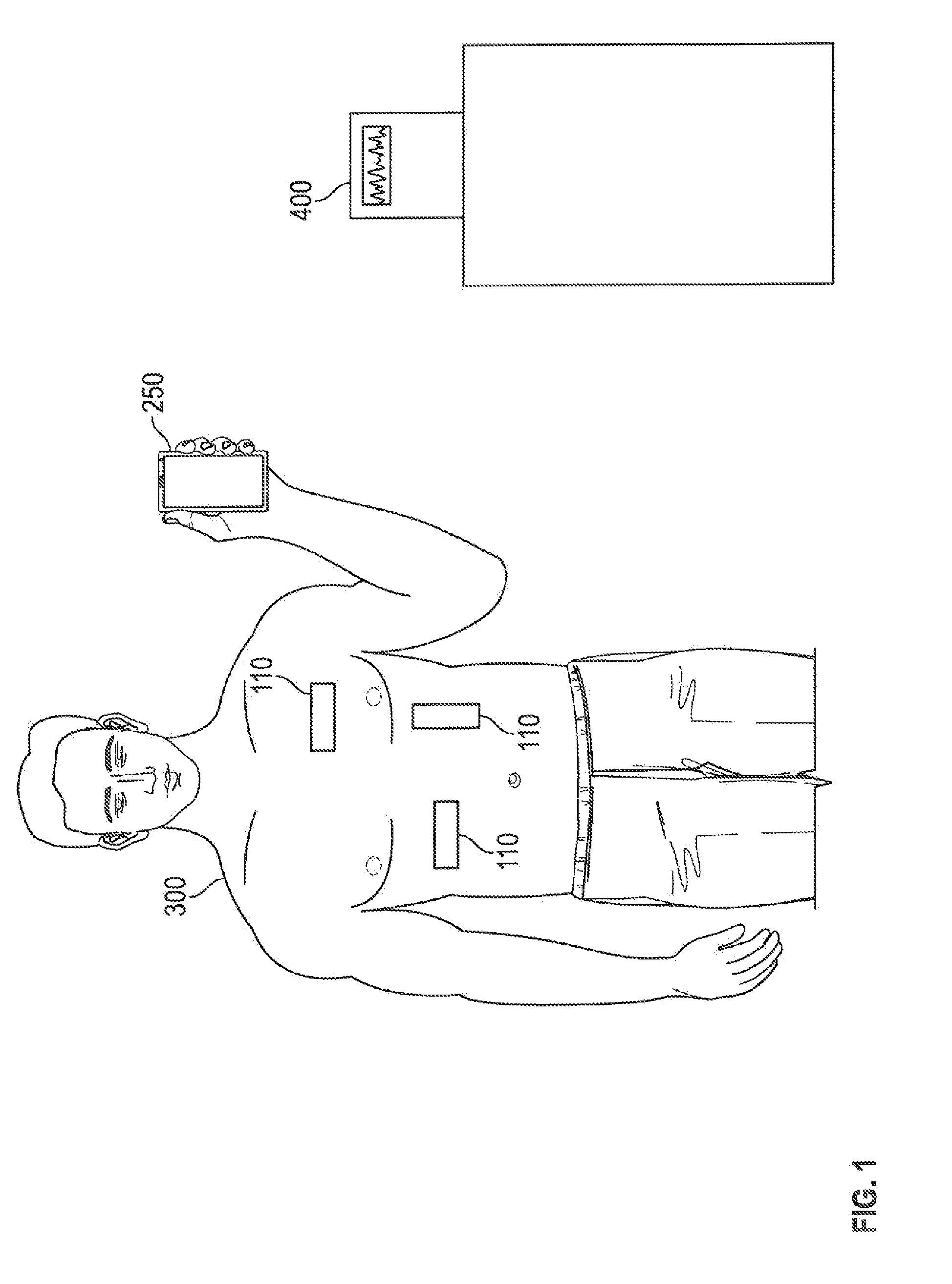
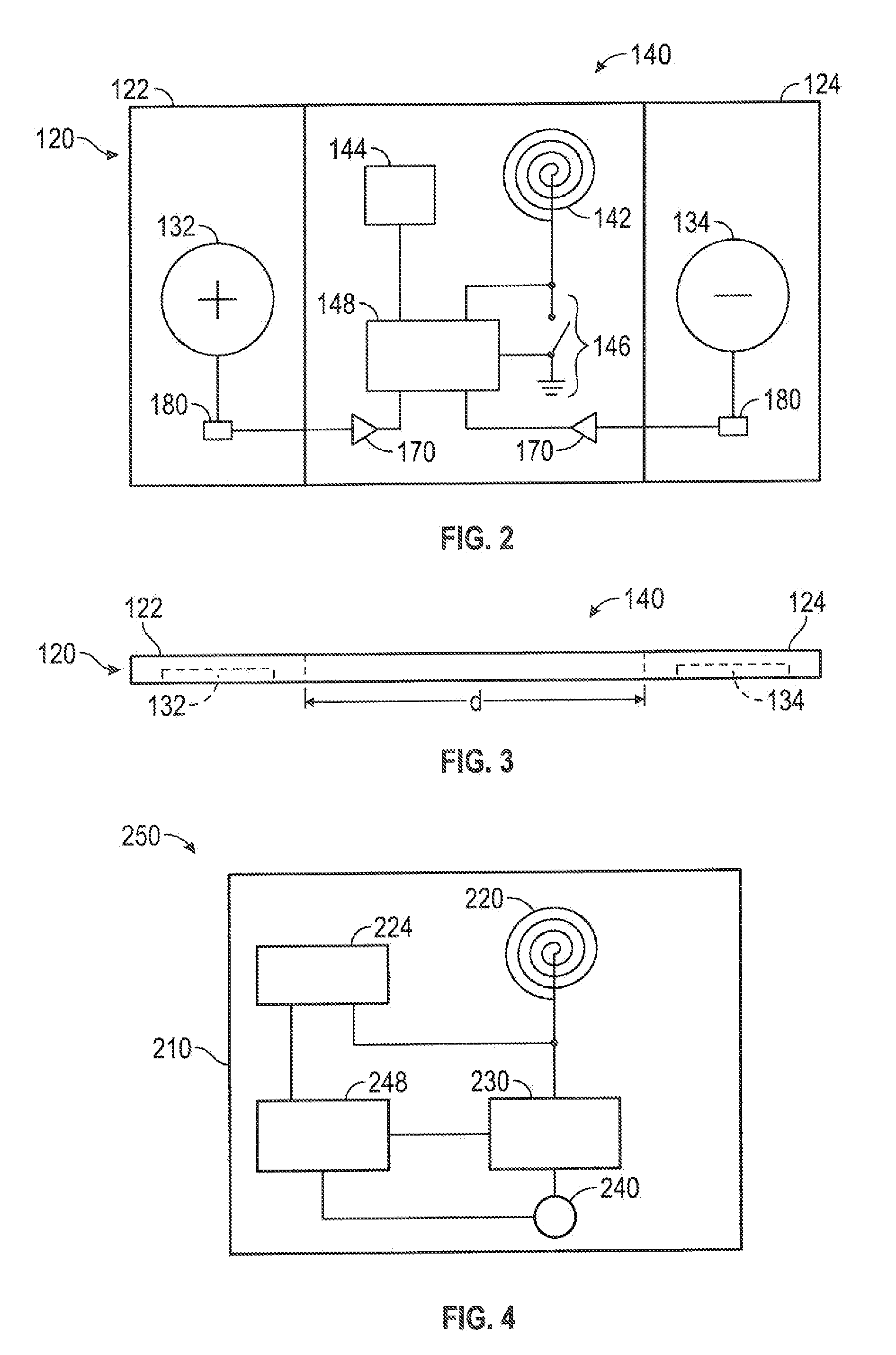
[0031]The present invention will now be described more fully hereinafter with reference to the accompanying drawings, in which preferred embodiments of the invention are shown. This invention may, however, be embodied in many different forms and should not be construed as limited to the embodiments set forth herein. Rather, these embodiments are provided so that this disclosure will be thorough and complete, and will fully convey the scope of the invention to those skilled in the art. Those of ordinary skill in the art realize that the following descriptions of the embodiments of the present invention are illustrative and are not intended to be limiting in any way. Other embodiments of the present invention will readily suggest themselves to such skilled persons having the benefit of this disclosure. Like numbers refer to like elements throughout.

[0032]Although the following detailed description contains many specifics for the purposes of illustration, anyone of ordinary skill in th...


PUM


Abstract

A wireless ECG sensor system includes a sensor patch configured to attach to a user. The sensor patch may include a substrate having a positive and a negative electrode, and a passive radio-frequency identification (RFID) transponder carried by the substrate. The RFID may include a first antenna, a non-transitory and non-volatile storage medium in, electrical communication with the first antenna, a load modulation switch in electrical communication with the first antenna, and a microcontroller in electrical communication with the first antenna and in data communication with both the storage medium and the load modulation switch. The system may also include an interrogator device having a second antenna configured to wirelessly transmit electromagnetic radiation having a resonant frequency of the first antenna of the sensor patch, and a demodulator configured to measure a voltage amplitude of the electromagnetic radiation wirelessly transmitted by the second antenna.

Description

FIELD OF THE INVENTION[0001]The present invention relates to systems and methods relating to wireless electrodes used to detect electrical signals from a subject patient.BACKGROUND[0002]Conventionally, electrodes are attached to a patient's skin and used for detecting electrical impulses in a patient. These electrical impulses may be used, for example, to produce an electrocardiogram (ECG).[0003]These conventional electrodes have wired connections extending from the electrode a receiving device. The electrical signal received by the electrode is sent along a wire and is then amplified and read by the receiving device. Thus, while an ECG is being taken, the patient must remain physically connected to the monitoring device.[0004]The use of wired connections means that the electrode may become unplugged due to patient or other movement. Also, having wired connections tethers a patient to a particular piece of machinery, limiting patient mobility or requiring suspending detection using ...

Claims


Application Information

Patent Timeline
Patent Type & Authority Applications(United States)
IPC IPC(8): A61B5/00A61B5/0452A61B5/0428A61B5/0408A61B5/04A61B5/296A61B5/308A61B5/332G16H40/67G16Z99/00
CPCA61B5/0006A61B5/04087A61B5/04085A61B5/7228A61B2560/0214A61B5/04286A61B5/002A61B5/6898A61B5/0452A61B5/04012A61B5/6833A61N1/3727A61N1/37288A61B5/0022A61B5/0024A61B2560/0219A61B2562/08A61N1/0492G16H40/67A61B5/332G16Z99/00A61B5/259A61B5/282A61B5/303A61B5/316A61B5/318A61B5/349G16H15/00G16H10/60
Inventor MARCUS, SEANCHANG, CHRISBASKERVILLE, SCOTT
Owner MEDICOMP
Learn More