
Method of tethering a tool

Active Publication Date: 2016-09-08
PURE SAFETY GRP INC
View PDF14 Cites 11 Cited by
  • Summary
  • Abstract
  • Description
  • Claims
  • Application Information

AI Technical Summary

Benefits of technology

The present invention provides an improved method for tethering tools, wrenches, pipes, and other objects that lack geometry necessary for securing a connector strap. The method involves using a web tail or other connector strap to secure the tools. This method increases failure resistance compared to prior art methods involving heat-shrink tubing or self-amalgamating tape applied over a connector strap that is positioned in direct contact with the tool.

Problems solved by technology

The above-described methods of tethering a tool using a web tail-type connector strap and heat shrink tubing or tape has been found unsatisfactory for tools weighing more than five pounds.
Attaching web tails to specialty tools, such as spud wrenches, is also problematic because the heat shrink tubing can slide off the end of a straight or tapered handle.
Thus, deficiencies in tethering methods using tape or heat-shrink tubing alone to secure a web tail to the tool render these methods unsuitable for certain situations, such as for heavier tools or for tools having a tapered end that allows the web tail to slide off of the end of the tool.

Method used


Image

  • Method of tethering a tool
  • Method of tethering a tool
  • Method of tethering a tool

Examples


Embodiment Construction

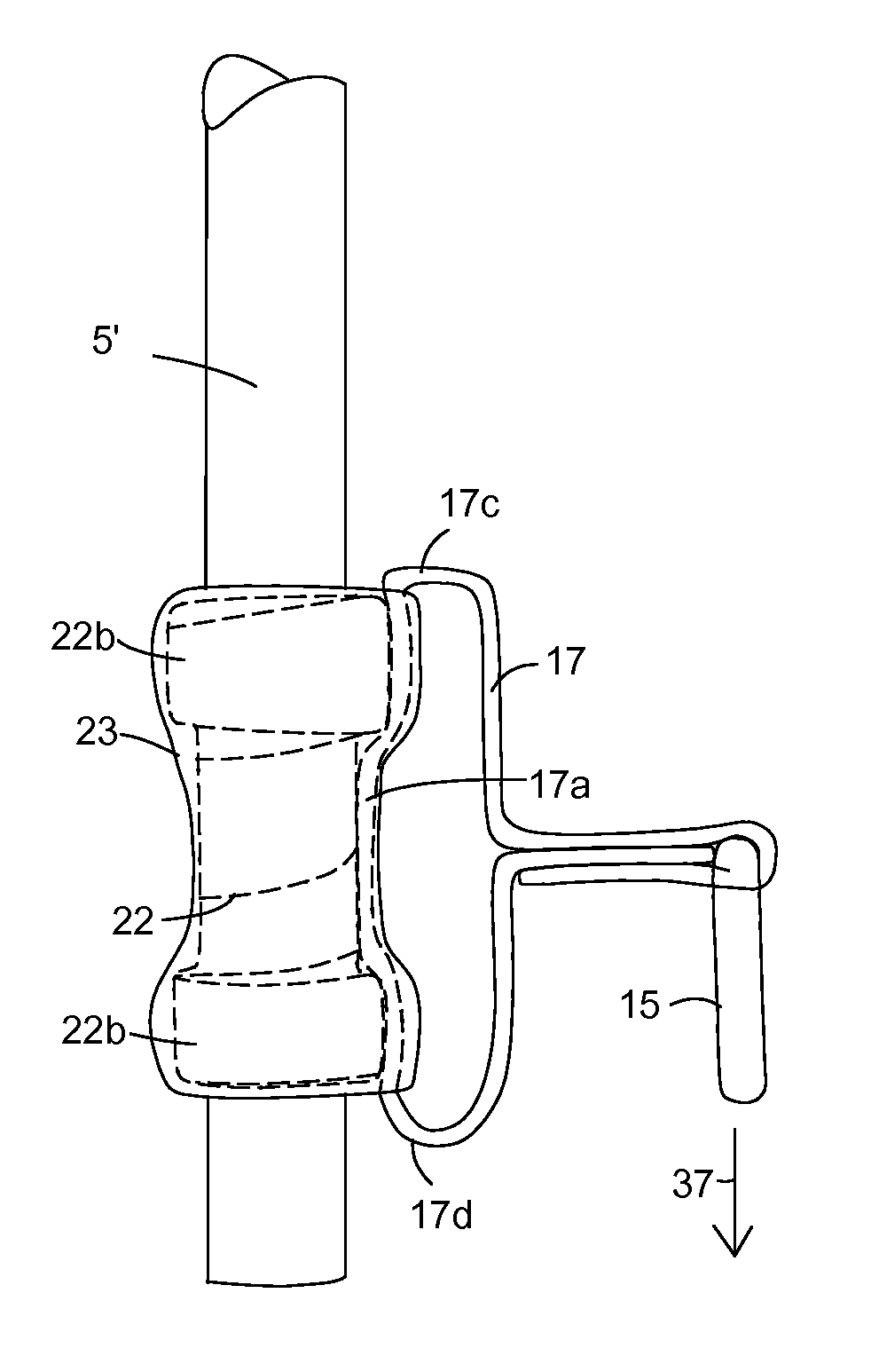
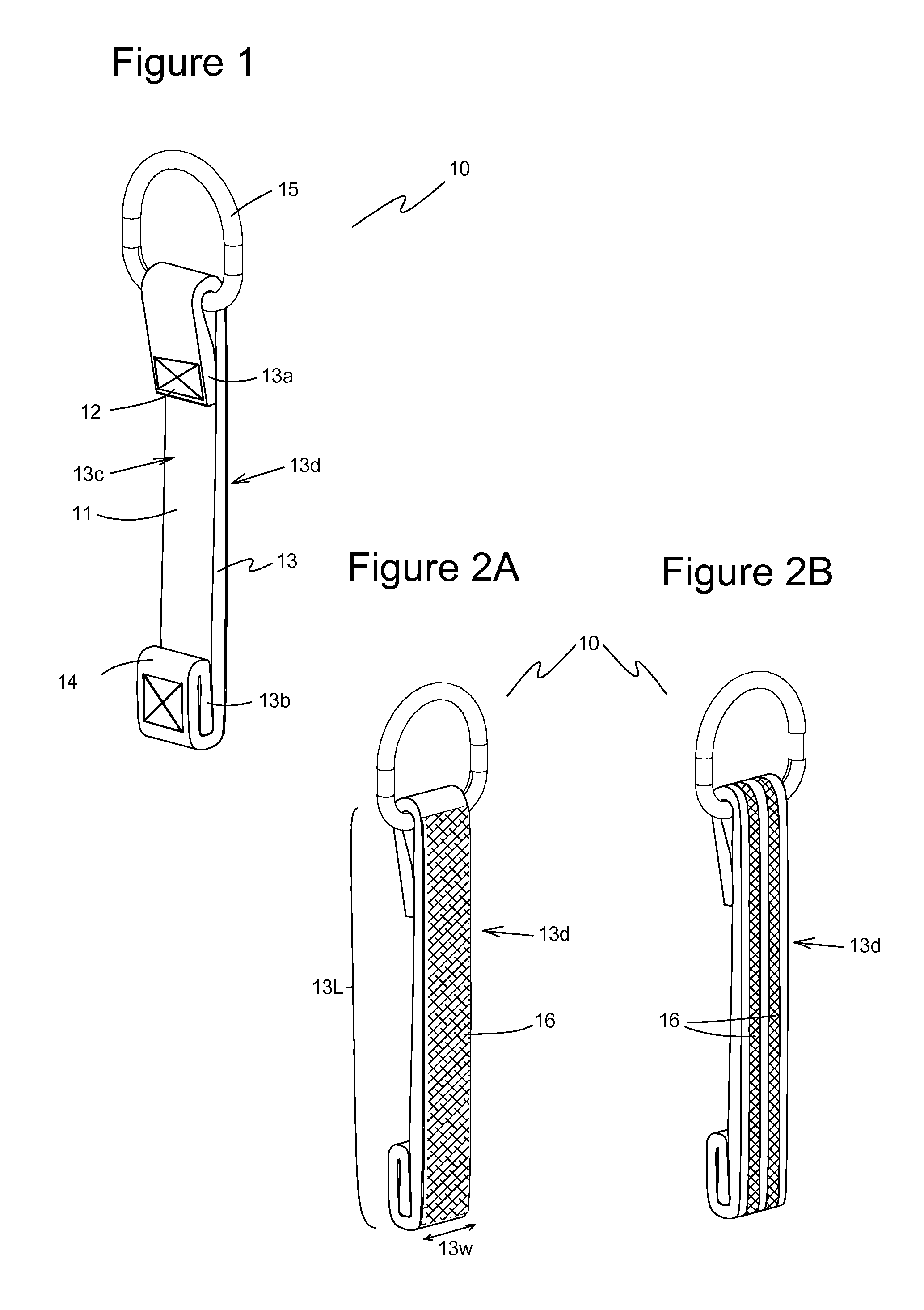
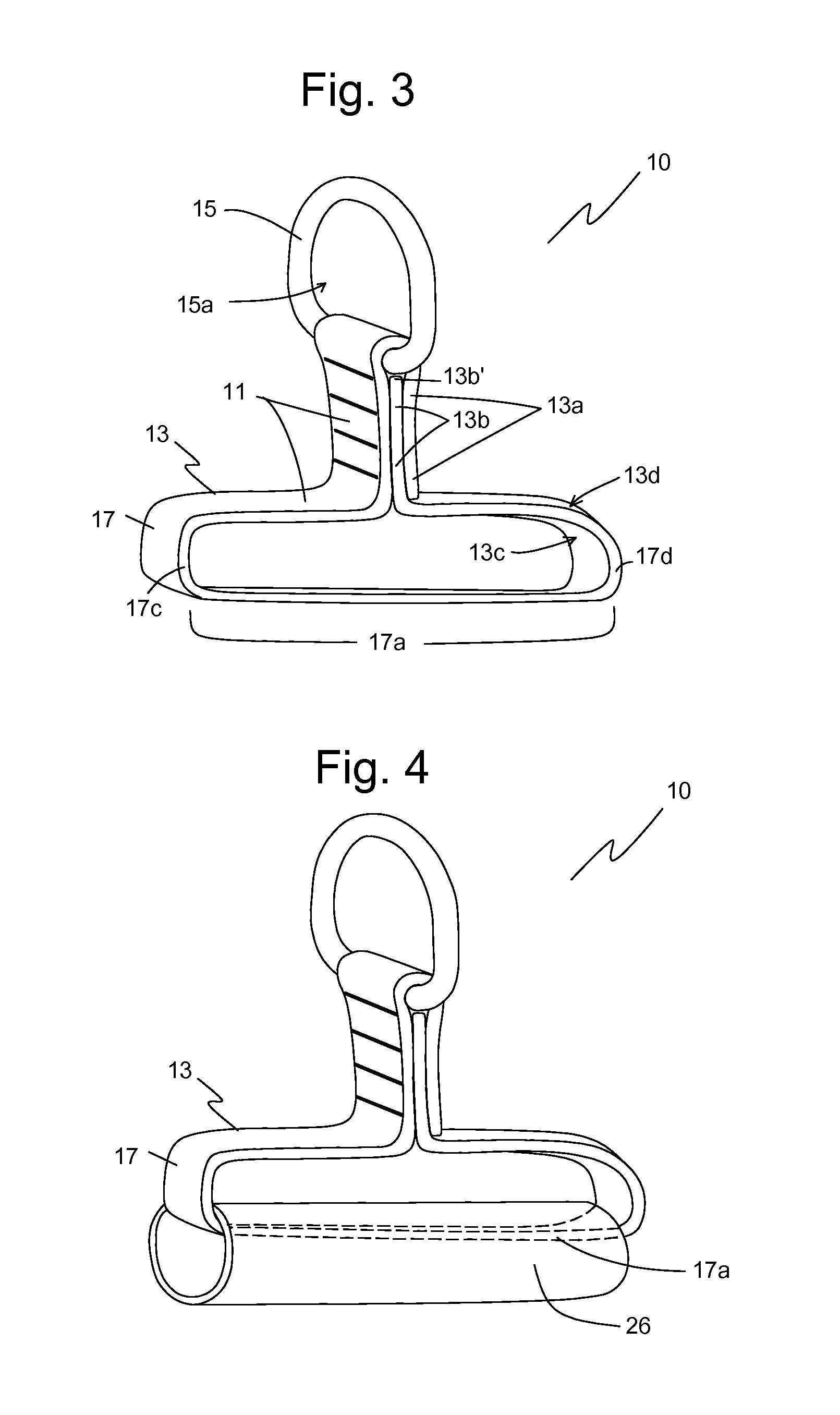
[0055]Embodiments of the present invention are illustrated in FIGS. 1-29. FIG. 1 illustrates a front perspective view of one embodiment of a connector strap 10 secured to a connector 15 suitable for attaching a tether (not shown). In the embodiment of FIG. 1, connector strap 10 includes a length of webbing 13 with a first end portion 13a, a second end portion 13b, a front surface 13c, and a back surface 13d. In one embodiment, first end portion 13a defines a first catch 12 and second end portion 13b defines a second catch 14, where body portion 11 is between first catch 12 and second catch 14.

[0056]In one embodiment, connector 15 defines a closed-loop and connector 15 is secured to webbing 13 by looping first end portion 13a through the closed-loop and securing first end portion 13a to body portion 11, such as by stitching, fasteners, adhesive or other means. Also, by attaching first end portion 13a to webbing 13 in this manner, first end portion 13a defines a first catch 12 on fron...


PUM

PropertyMeasurementUnit
Lengthaaaaaaaaaa
Flexibilityaaaaaaaaaa
Distanceaaaaaaaaaa

Abstract

A tool tethering method includes the steps of providing a tool with a longitudinal portion, installing a base layer on the longitudinal portion, providing an overwrap member, and providing a connector strap. The connector strap includes a length of webbing secured to a connector and defining a first catch and a second catch. The connector strap is positioned with the body portion axially aligned with the longitudinal portion of the tool, with the first catch and the second catch facing away from the longitudinal portion, and with the back surface in contact with the base layer. The overwrap member is installed over the body portion of the connector strap and the corresponding region of the longitudinal portion of the tool and base layer, thereby securing the connector strap to the tool.

Description

BACKGROUND OF THE INVENTION[0001]1. Field of the Invention[0002]The present invention relates generally to drop-prevention equipment and methods. More particularly, the present invention relates to a method of tethering a tool using a connector strap.[0003]2. Description of the Prior Art[0004]Lanyards, tethers, hooks, and similar restraints are used to prevent the accidental dropping of tools. These restraints are particularly useful for workers at height and in environments where a tool drop can cause substantial damage or harm to equipment, to workers, or to objects below a worker who accidentally drops a tool.[0005]One method of tethering a tool includes clipping one end of a tether to an opening in the handle of a tool (e.g., an adjustable wrench) and to clip the other end of the tether to the worker's belt or to a nearby structure. When workers properly tether a tool in this way, accidental drops can be eliminated or substantially reduced.[0006]Some tools and equipment lack an ...

Claims


Application Information

Patent Timeline
IPC IPC(8): B29C65/68B29C65/50F16L3/02B29C65/00
CPCB29C65/68B29C66/532B29L2023/22B29C65/5057F16L3/02B29C65/5042B25H3/00
Inventor MOREAU, DARRELL A.MOREAU, ANDRE W.
Owner PURE SAFETY GRP INC
Learn More