
Surgical cannula with channels for irrigation and suction

a surgical cannula and suction technology, applied in the field of surgical cannulas, can solve the problems of clamping arms, partially dislodging, and affecting the operation efficiency of surgeons,

Inactive Publication Date: 2016-09-08
MEDTRONIC HLDG CO SARL +1
View PDF6 Cites 1 Cited by
  • Summary
  • Abstract
  • Description
  • Claims
  • Application Information

AI Technical Summary

Benefits of technology

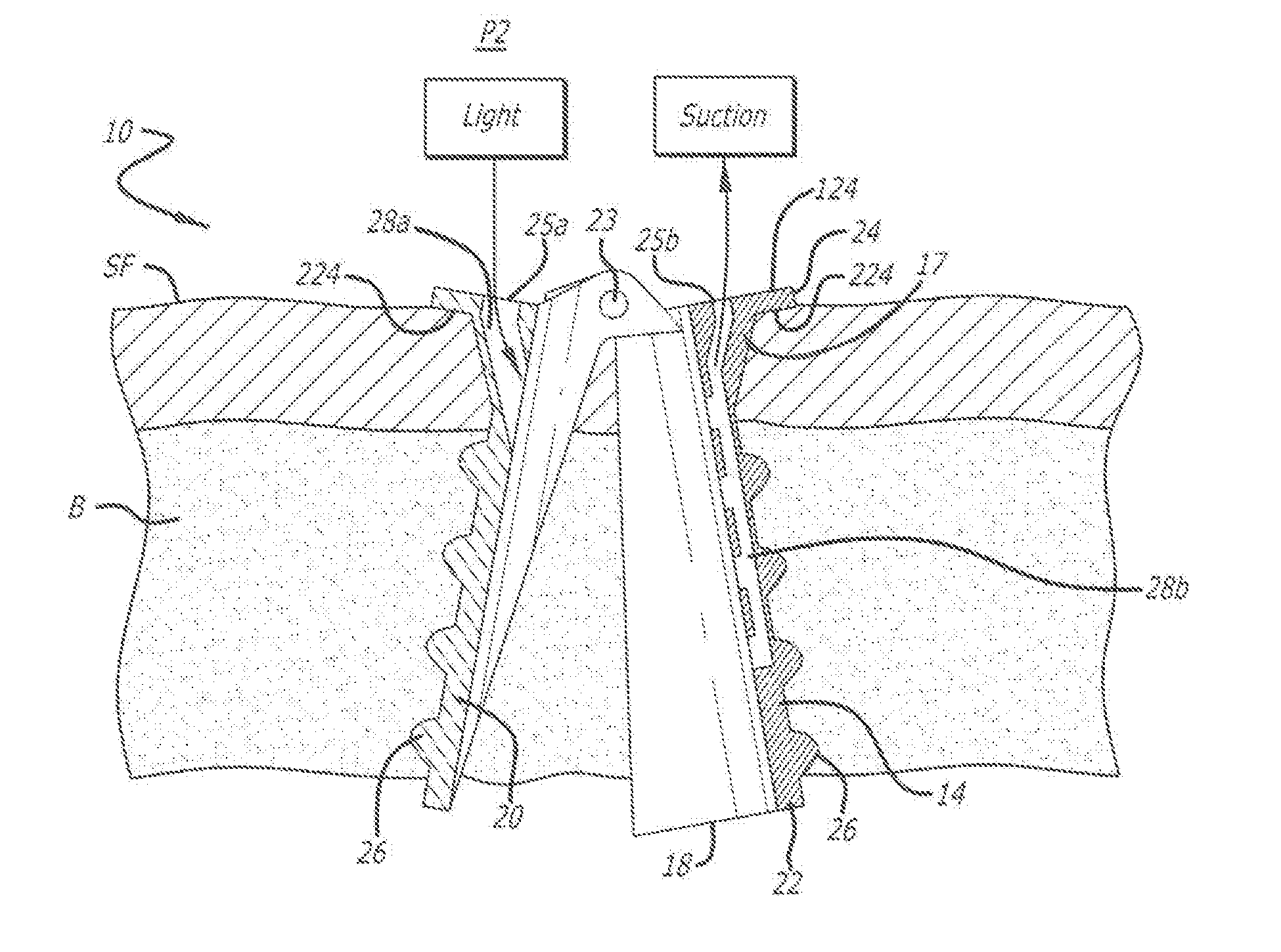
The surgical cannula described in the patent has a flange with at least one channel that connects to the surgical site. The channel can be used to provide excess light, irrigation liquid, or suction to remove material that may be obstructing the surgeon's view. This improves visibility and makes the surgery safer.

Problems solved by technology

For example, the diameters of conventional cannulas typically are too small to provide surgeons with unimpeded access to surgical sites.
Use of such external clamping arms requires the patient to be placed under full anesthesia, since movement by the patient during the surgical procedure can cause the clamping arms to move, or even partially dislodge, the conventional cannula.
Additional shortcomings with the conventional surgical cannulas include: (1) it is sometimes difficult for surgeons to clearly see the respective surgical sites through the cannulas; (2) it is difficult to provide irrigation liquid to the surgical site; (3) when burrs are used to remove interfering bone near the respective surgical site, smoke, bone dust, and sometimes blood and other tissue further obscure visibility of the surgical site.

Method used


Image

  • Surgical cannula with channels for irrigation and suction
  • Surgical cannula with channels for irrigation and suction
  • Surgical cannula with channels for irrigation and suction

Examples


Embodiment Construction

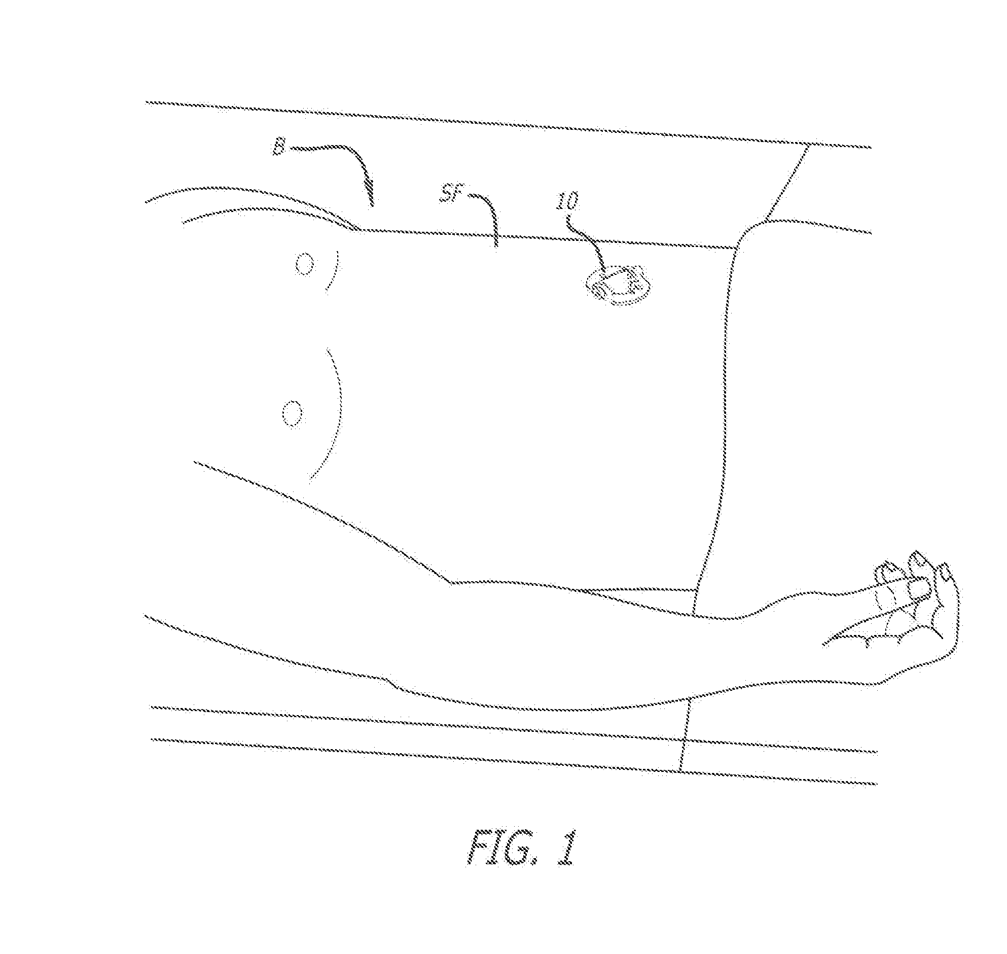
[0019]In accordance with the present invention, a surgical cannula 10, as depicted in FIG. 1, is provided for accessing a surgical site in the body B of a patient.

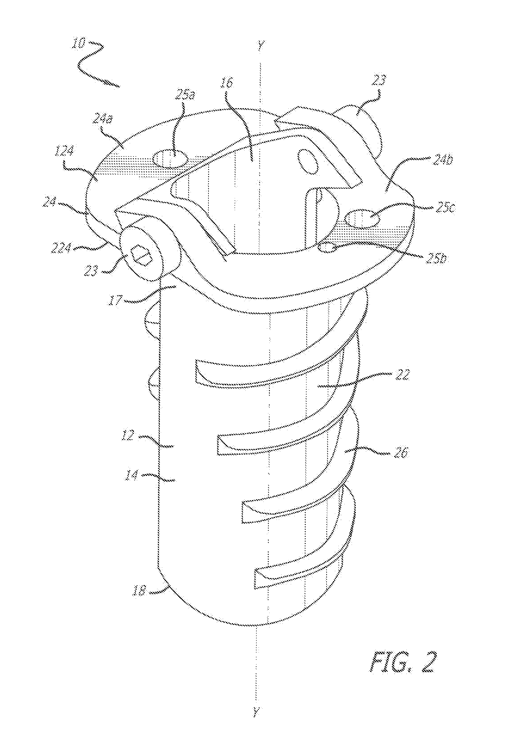
[0020]Referring to FIGS. 2, 3, 5, and 6, the surgical cannula 10 includes a cannula body 12 that can be substantially cylindrical, having a central longitudinal axis Y-Y and an external peripheral surface 14. The cannula body 12 has a bore 16, a proximal end 17, a distal end 18, and a length between the proximal end and the distal end. The bore 16 can be coaxial with central longitudinal axis Y-Y, and can extend centrally through the cannula body 12. The length is long enough such that the surgical cannula 10, when inserted into the patient's body B (FIG. 1), can extend from a superficial fascia SF of the patient's body B above the surgical site to at least adjacent the surgical site.

[0021]As depicted in FIGS. 2, 3, 5, and 6, the cannula body 12 defined by a first cannula body portion 20 and a second cannula body portion 2...


PUM


Abstract

A surgical cannula for providing access to a surgical site in a patient's body. A cannula body of the surgical cannula has a flange attached to a proximal end. The cannula body is defined by two complementary portions, pivotally connected together proximate the flange. The cannula body has a bore extending from the flange to the surgical site. The cannula is inserted into the patient's body above the surgical site, until a lower surface of the flange contacts the patient's superficial fascia, which acts as a stop to prevent over-insertion. A thread provided on the cannula body holds the cannula in position in the patient's body. Apertures in the flange communicate with channels within the cannula body that extend to the surgical site to provide the surgeon with additional means to provide light, irrigation, and / or suction to and from the surgical site. The two complimentary portions can be pivoted apart from one another within the patient's body to provide an increased amount of access to the surgical site.

Description

BACKGROUND OF THE INVENTION[0001]The present invention relates to a surgical cannula used during the performance of a surgical procedure on a patient. More particularly, the present invention relates to a surgical cannula which is configured to spread open inside the patient to provide the surgeon with more unimpeded access to the surgical site; is configured to be held in place within the patient's body with limited, if any, assistance of external structures; is configured to limit a depth of insertion into the patient's body; and is configured with channels to light the operating site, and to irrigate and remove from the surgical site irrigation liquid and other unwanted materials.DESCRIPTION OF THE PRIOR ART[0002]Surgical cannulas are known to provide access to a surgical site, e.g., a human spine. Such cannulas can be inserted into the patient's body during a surgical procedure either from an anterior approach or a posterior approach to provide access to the surgical site. Conve...

Claims


Application Information

Patent Timeline
Patent Type & Authority Applications(United States)
IPC IPC(8): A61B17/34A61B19/00
CPCA61B17/3423A61B19/5202A61B2217/007A61B2217/005A61B2017/3458A61B17/02A61B17/0206A61B17/3439A61B2090/306A61B2090/309A61B2090/3614A61B90/30
Inventor TONTZ, WILLIAM
Owner MEDTRONIC HLDG CO SARL
Learn More