
Magnetic pressure jacket for fluid injector

Active Publication Date: 2016-09-01
BAYER HEALTHCARE LLC
View PDF2 Cites 0 Cited by
  • Summary
  • Abstract
  • Description
  • Claims
  • Application Information

AI Technical Summary

Benefits of technology

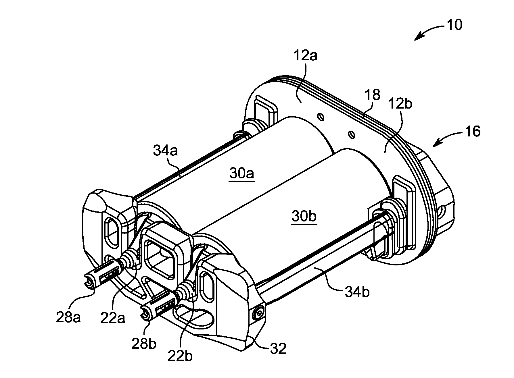
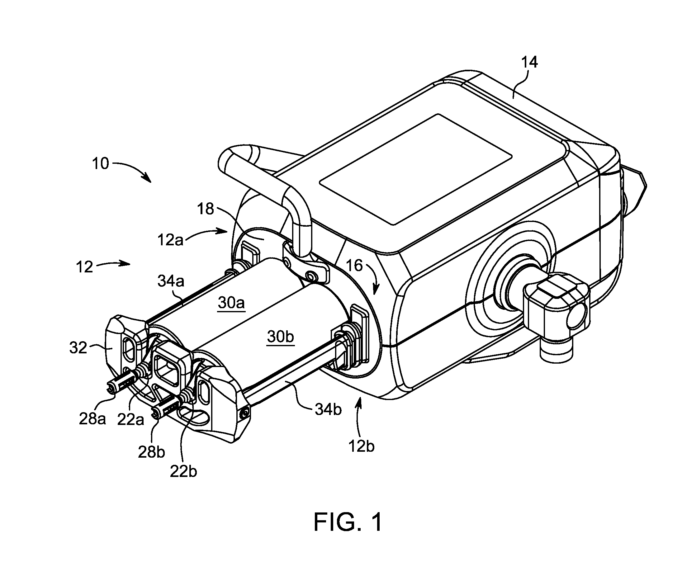
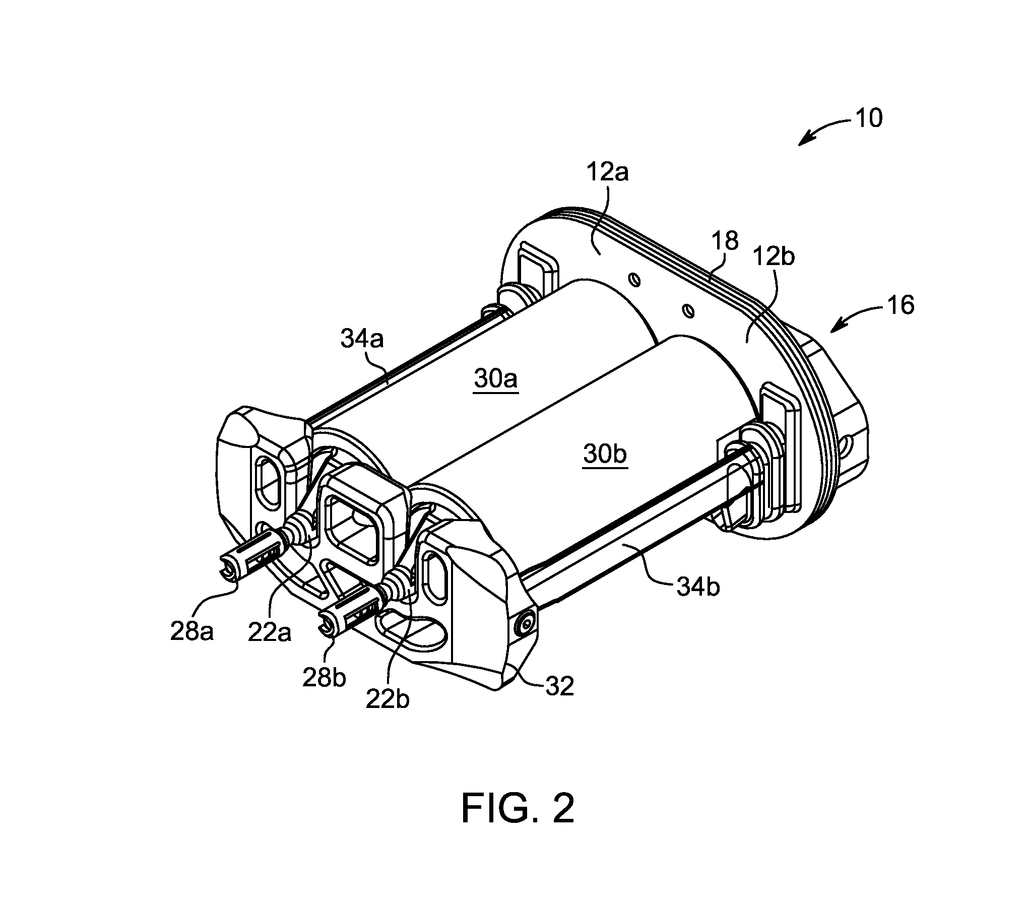
The patent text describes an improved fluid injector with a pressure jacket for securing a syringe during an injection procedure. The injector has a front end for receiving the syringe and a pressure jacket that can be releasably connected to the injector head using a connection mechanism. The connection mechanism includes at least one magnet to facilitate the connection. The injector head can be pivotally connected to the pressure jacket to allow for a relative motion between the two during the injection procedure. The pressure jacket can be retained in a first position using an arm and a holding bracket, which can be magnetically retained. The technical effects of the patent text include improved fluid injector with a pressure jacket for secure injection, simplified connection mechanism, and improved portability of the fluid delivery system.

Problems solved by technology

Excessive radial expansion of the syringe may lead to bursting or to leaks of the pressurized fluid around the seals of the syringe plunger.
Additionally, the syringe and / or the pressure jacket may experience significant axial movement during a high pressure injection due to the elastic nature of the structural components restraining the syringe.
However, such an arrangement is associated with a number of disadvantages.
Fluid spilled during loading of the syringe and purging of air from the syringe may get inside the pressure jacket and the circumferential groove, thereby complicating the cleaning procedure.
Such axial stress can sometimes lead to slipping of the pressure jacket during the injection procedure, which may result in a loud and unsettling noise.
In addition, continuous installation and removal of the pressure jacket from the injector head can cause significant wear on the circumferential groove.

Method used


Image

  • Magnetic pressure jacket for fluid injector
  • Magnetic pressure jacket for fluid injector
  • Magnetic pressure jacket for fluid injector

Examples


Embodiment Construction

[0027]For purposes of the description hereinafter, spatial orientation terms shall relate to the referenced embodiments as they are oriented in the drawing figures. For example, the terms “upper”, “lower”, “right”, “left”, “vertical”, “horizontal”, “top”, “bottom”, “lateral”, “longitudinal”, and derivatives thereof shall relate to the embodiments as they are oriented in the drawing figures. When used in relation to the syringe and / or the pressure jacket, the term “proximal” refers to the portion of the syringe and / or the pressure jacket nearest the fluid injector when the syringe and / or pressure jacket is oriented for connecting to the fluid injector. The term “distal” refers to the portion of the syringe and / or pressure jacket farthest away from the fluid injector when the syringe and / or pressure jacket is oriented for connecting to the fluid injector. It is to be understood, however, that the disclosure may assume alternative variations and step sequences, except where expressly s...


PUM


Abstract

A fluid injector for use with at least one syringe has at least one injector head with a front end configured to releasably receive the at least one syringe. The fluid injector further includes at least one pressure jacket releasably associated with the front end of the at least one injector head for securing the at least one syringe during an injection procedure. A connection mechanism releasably connects the at least one pressure jacket to the front end of the at least one injector head. The connection mechanism includes at least one magnet. The at least one injector head has the at least one magnet while the at least one pressure jacket has a ferromagnetic material configured for magnetically interacting with the at least one magnet.

Description

CROSS-REFERENCE TO RELATED APPLICATIONS[0001]This application claims priority to U.S. Provisional Application No. 61 / 892,820, entitled “Magnetic Pressure Jacket for Dual Head Injector” and filed on Oct. 18, 2013. The disclosure of which is incorporated by reference herein in its entirety.BACKGROUND OF THE DISCLOSURE[0002]1. Field of the Disclosure[0003]The present disclosure is directed to medical fluid delivery applications and, particularly, to a magnetically-retained pressure jacket configured for use with a fluid injector.[0004]2. Description of Related Art[0005]In the medical field, patients often are injected with one or more medical fluids in various procedures. In such procedures, which require a controlled injection of a volume of one or more fluids into a patient, a needle is used as a conduit for the fluid and is connected to a syringe by a connector tube. One or more syringes may be mounted on a motorized fluid injector having one or more injector heads. In some embodime...

Claims


Application Information

Patent Timeline
IPC IPC(8): A61M5/00A61M5/20
CPCA61M5/007A61M2209/082A61M5/20A61M5/14546A61M5/14566A61M2005/14553A61M2005/14573
Inventor DEDIG, JAMES A.SCHRIVER, RALPH H.CAMPBELL, PATRICK B.GRUBIC, HERBERT M.
Owner BAYER HEALTHCARE LLC
Learn More