
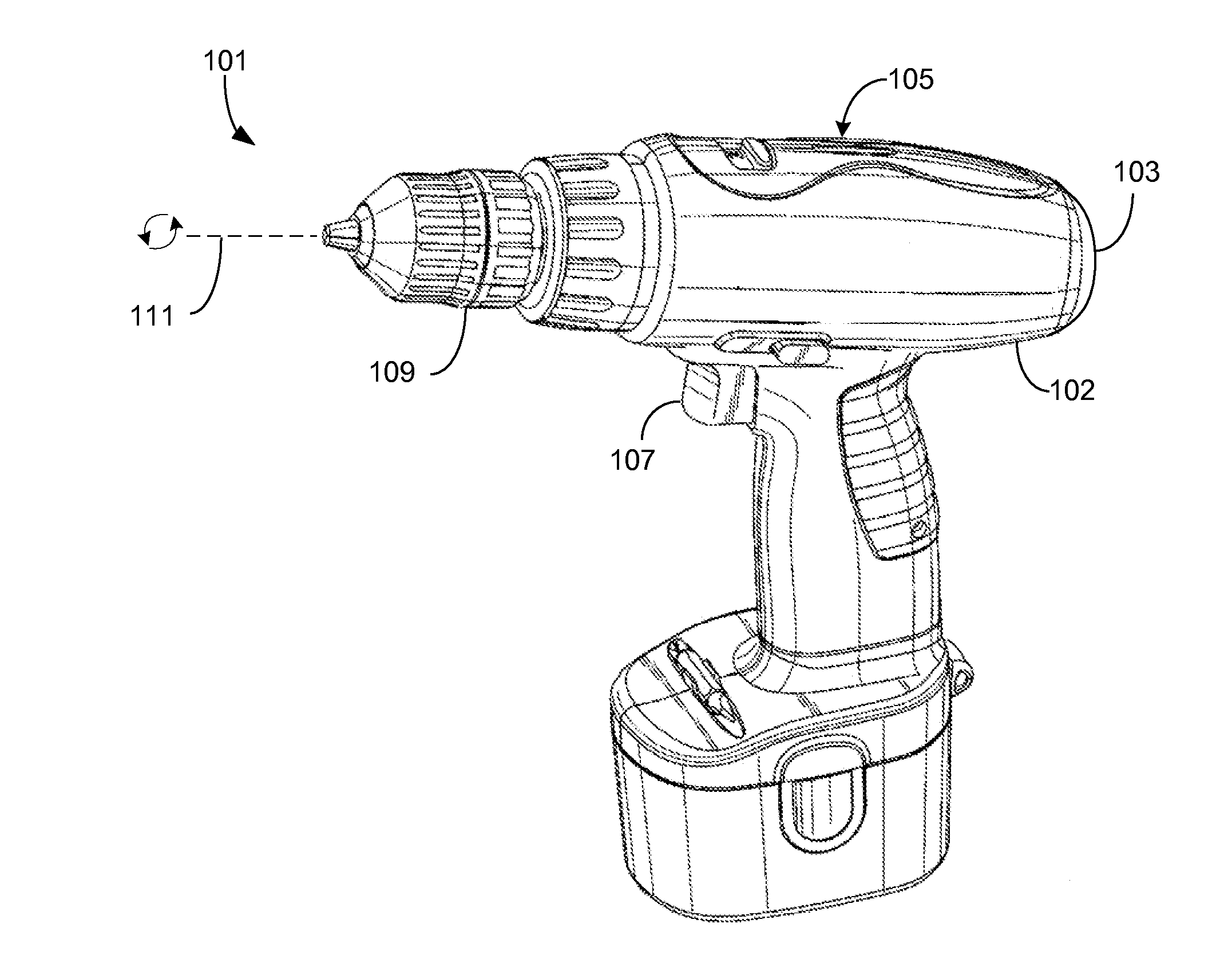
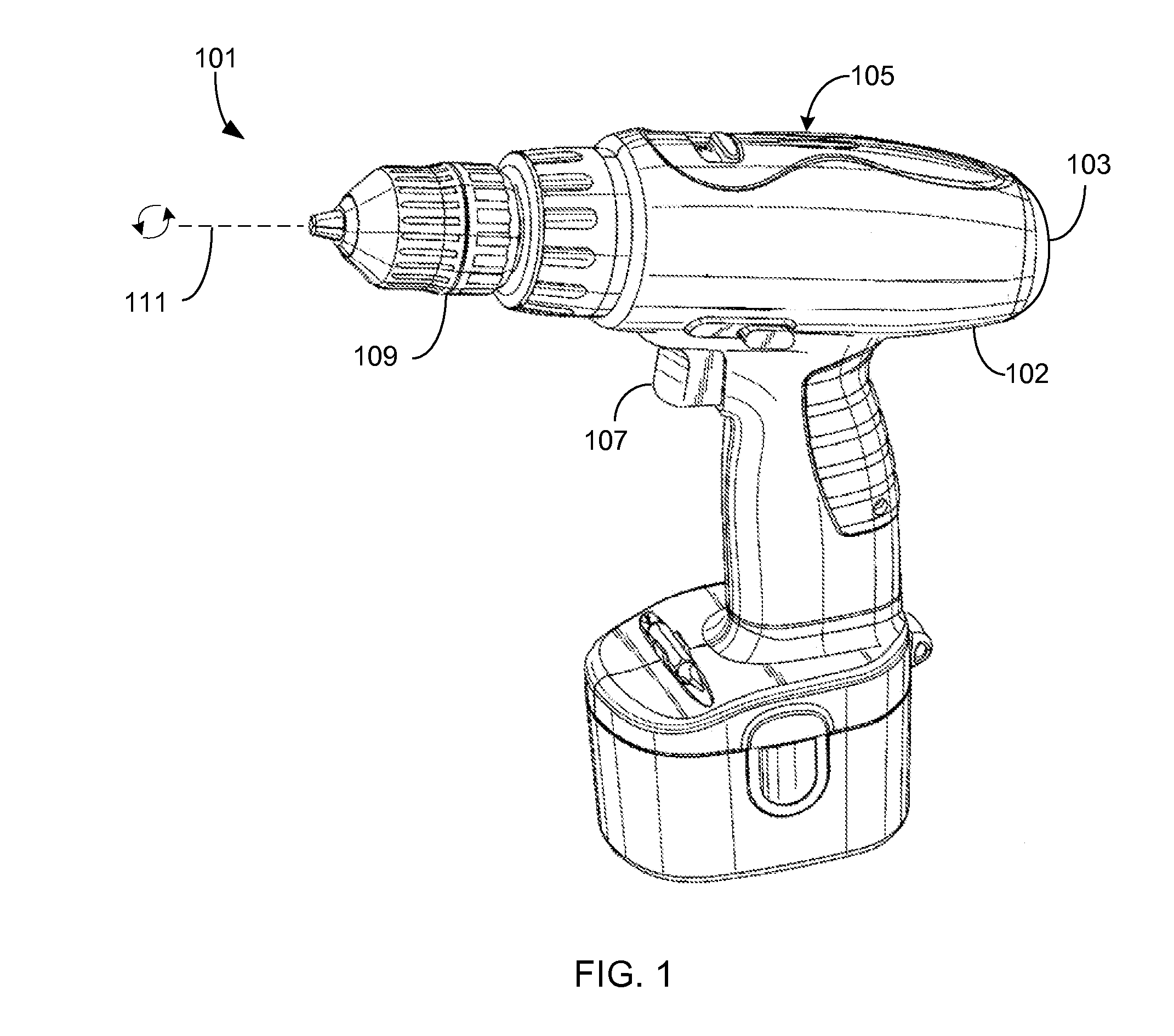
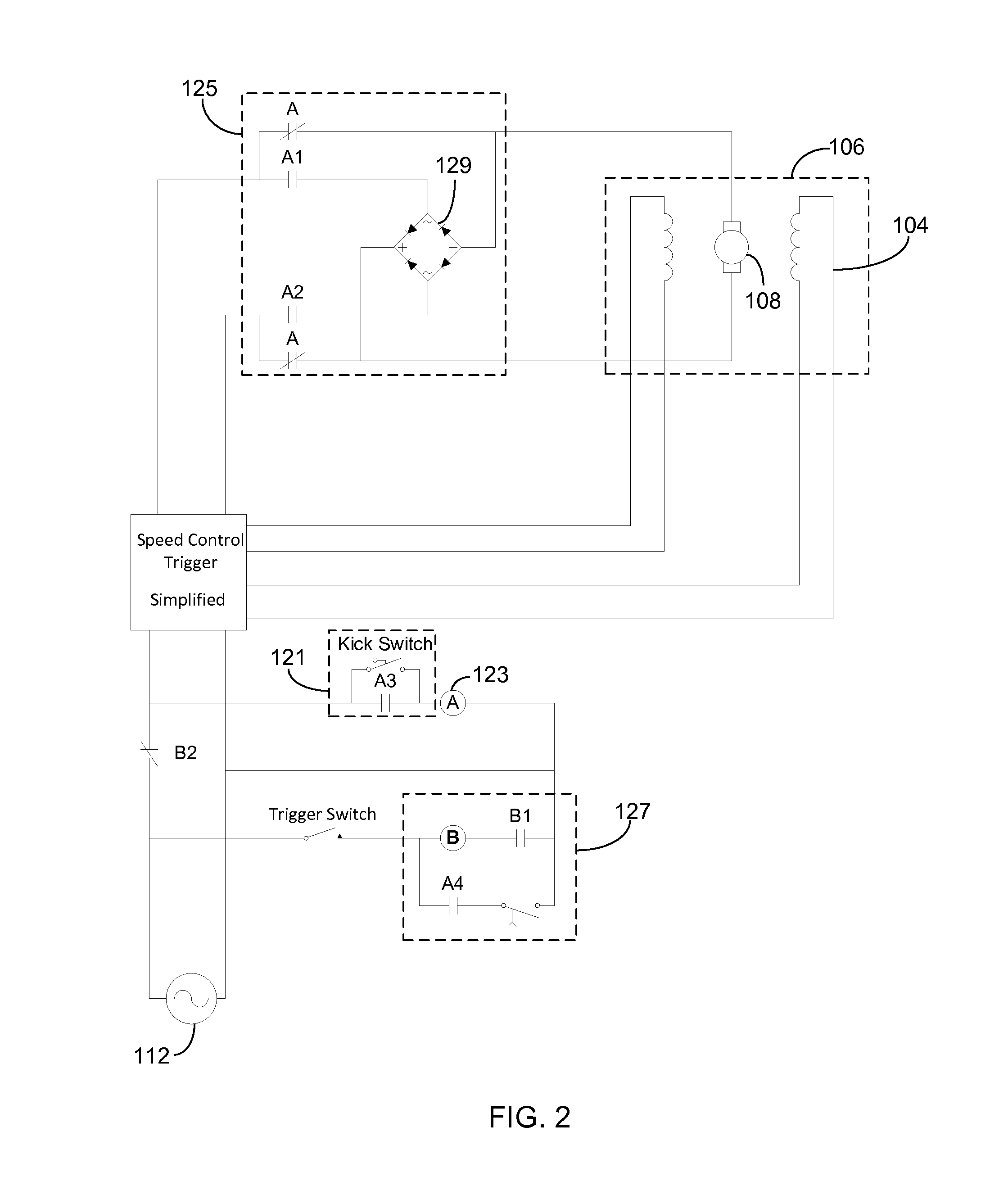
Anti-torqueing dynamic arresting mechanism

a dynamic arresting mechanism and anti-torque technology, applied in the direction of metal-working machine components, metal-working apparatus, maintainance and safety accessories, etc., can solve the problems of operators being injured, rotating power tools or hand tools suddenly experiencing an impending kickback condition

Active Publication Date: 2016-08-25
PATTERSON JAMES
View PDF3 Cites 2 Cited by
  • Summary
  • Abstract
  • Description
  • Claims
  • Application Information

AI Technical Summary

Benefits of technology

The present patent is about a mechanism for stopping the sudden and unexpected rotation of hand tools, which can cause injury to operators. The mechanism is designed to apply a dynamic brake to the motor of the rotating tool so as to stop the torque of the motor and prevent the tool body from rotating. This mechanism can be simple and effective without the need for complex circuitry. It is designed to be effective in preventing bodily injury caused by twisting motions and other injuries associated with the use of rotating tools.

Problems solved by technology

Generally speaking, rotating power tools or hand tools may suddenly experience an impending kickback condition at which time the spindle quickly slows or ceases rotation and the torque of the motor is suddenly passed to the body of the tool.
Sudden rotation of the tool body can cause injuries to operators.

Method used


Image

  • Anti-torqueing dynamic arresting mechanism
  • Anti-torqueing dynamic arresting mechanism
  • Anti-torqueing dynamic arresting mechanism

Examples


Embodiment Construction

[0012]Illustrative embodiments of the preferred embodiment are described below. In the interest of clarity, not all features of an actual implementation are described in this specification. It will of course be appreciated that in the development of any such actual embodiment, numerous implementation-specific decisions must be made to achieve the developer's specific goals, such as compliance with system-related and business-related constraints, which will vary from one implementation to another. Moreover, it will be appreciated that such a development effort might be complex and time-consuming but would nevertheless be a routine undertaking for those of ordinary skill in the art having the benefit of this disclosure.

[0013]In the specification, reference may be made to the spatial relationships between various components and to the spatial orientation of various aspects of components as the devices are depicted in the attached drawings. However, as will be recognized by those skille...


PUM


Abstract

A dynamic arresting mechanism for preventing injury from the torqueing of a rotating tool body. The mechanism including an inertia switch to automatically detect the rotation of the tool body and selectively initiate a dynamic arresting mechanism sequence configured to arrest the motor. The mechanism further including a first relay in communication with the inertia switch, an arresting mechanism configured to brake the rotation of the motor, and a delay mechanism configured to cut off power to the arresting mechanism and motor after a predetermined amount of time has elapsed. The mechanism is reset upon release of the trigger used to operate the rotating tool.

Description

BACKGROUND[0001]1. Field of the Invention[0002]The present application relates generally to drill devices and, more particularly, to an anti-torqueing arresting mechanism to stop the sudden and undesirable rotation of a tool.[0003]2. Description of Related Art[0004]Rotating hand tools are common place in today's society. Power tools typically employ a motor that imparts a torque to a tool through a spindle and associated gears or chuck. Examples of such devices are rotating drills, rotating screwdrivers, hole saws, grinding wheels, or other abrading tools.[0005]Generally speaking, rotating power tools or hand tools may suddenly experience an impending kickback condition at which time the spindle quickly slows or ceases rotation and the torque of the motor is suddenly passed to the body of the tool. The body then rotates about the axis of the spindle in place of the rotating spindle itself. Such conditions can commonly occur during binding of a bit, the setting of a screw, or during ...

Claims


Application Information

Patent Timeline
Patent Type & Authority Applications(United States)
IPC IPC(8): B25F5/00H02H7/085B23Q11/04
CPCB25F5/001H02H7/0856B23Q11/04
Inventor PATTERSON, JAMES
Owner PATTERSON JAMES
Learn More