A stereoscopic assembly and method for manufacturing same

a technology of stereoscopic components and assembly, which is applied in the field of optical devices, can solve the problems of difficult stereoscopic alignment of two camera units, high price of stereoscopic elements, and imposing mechanical limitations of optical requirements, so as to reduce the number of steps involved, reduce the cost involved, and minimize the offset/difference existing

Inactive Publication Date: 2016-08-18
INUITIVE
View PDF2 Cites 10 Cited by
  • Summary
  • Abstract
  • Description
  • Claims
  • Application Information

AI Technical Summary

Benefits of technology

The present disclosure provides a new optical module for mounting image capturing devices that reduces costs and offsets between modules. The method of manufacturing the optical module involves fewer steps for achieving stereoscopic alignment, and the resulting assembly has enhanced reliability and robustness. The optical module also reduces the calibration processes required during assembly. Additionally, the patent allows for a method of carrying out a focal adjustment on the stereo bench, which simplifies post processing tasks.

Problems solved by technology

The stereoscopic alignment of the two camera units is a challenging task, due to optical constraints on the one hand, versus mechanical limitations on the other hand.
However, the optical requirements impose quite severe mechanical limitations.
Having a precise assembly dictates costly processes, which result in high price of stereoscopic elements.
However, the solutions proposed in these attempts suffer from the following drawbacks:1. Active alignment is required in the process, in order to achieve a high degree of mutual alignment between the two cameras;2. The need to implement a multi-step assembly process by which the camera modules are first assembled.
For each step, high accuracy and very low tolerance of assembly must be followed.3. Since the stereo alignment outcome of this process is unpredicted due to accumulative offsets imposed by the various assembly tasks, extensive post, assembly calibration steps are required.4. Small footprint required by mobile services, resulting in a weak optic bench which affects the life time of the module.

Method used


Image

  • A stereoscopic assembly and method for manufacturing same
  • A stereoscopic assembly and method for manufacturing same
  • A stereoscopic assembly and method for manufacturing same

Examples


Embodiment Construction

[0045]In this disclosure, the term “comprising” is intended to have an open-ended meaning so that when a first element is stated as comprising a second element, the first element may also include one or more other elements that are not necessarily identified or described herein, or recited in the claims.

[0046]In the following description, for the purposes of explanation, numerous specific details are set forth in order to provide a better understanding of the present invention by way of examples. It should be apparent, however, that the present invention may be practiced without these specific details.

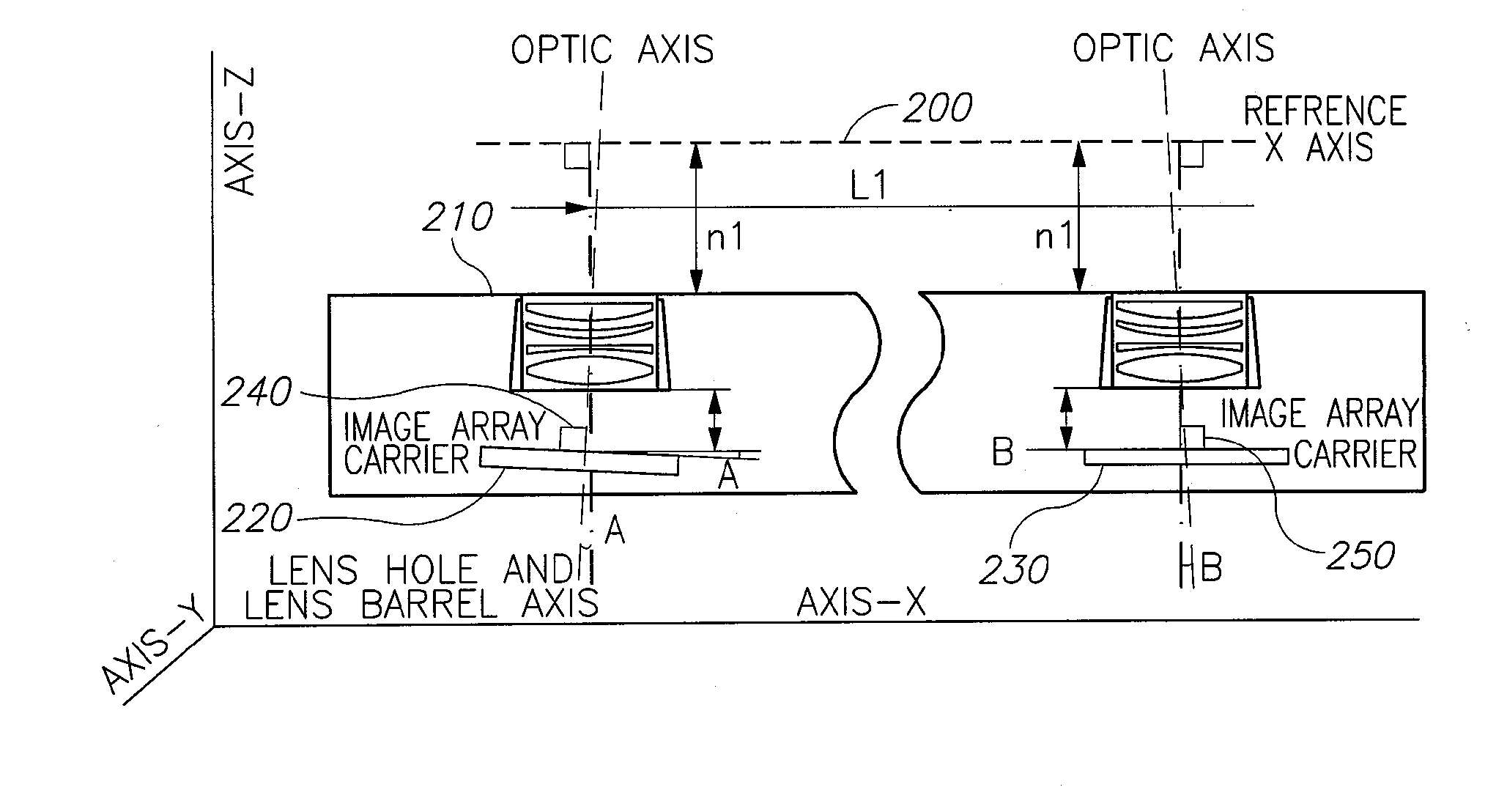
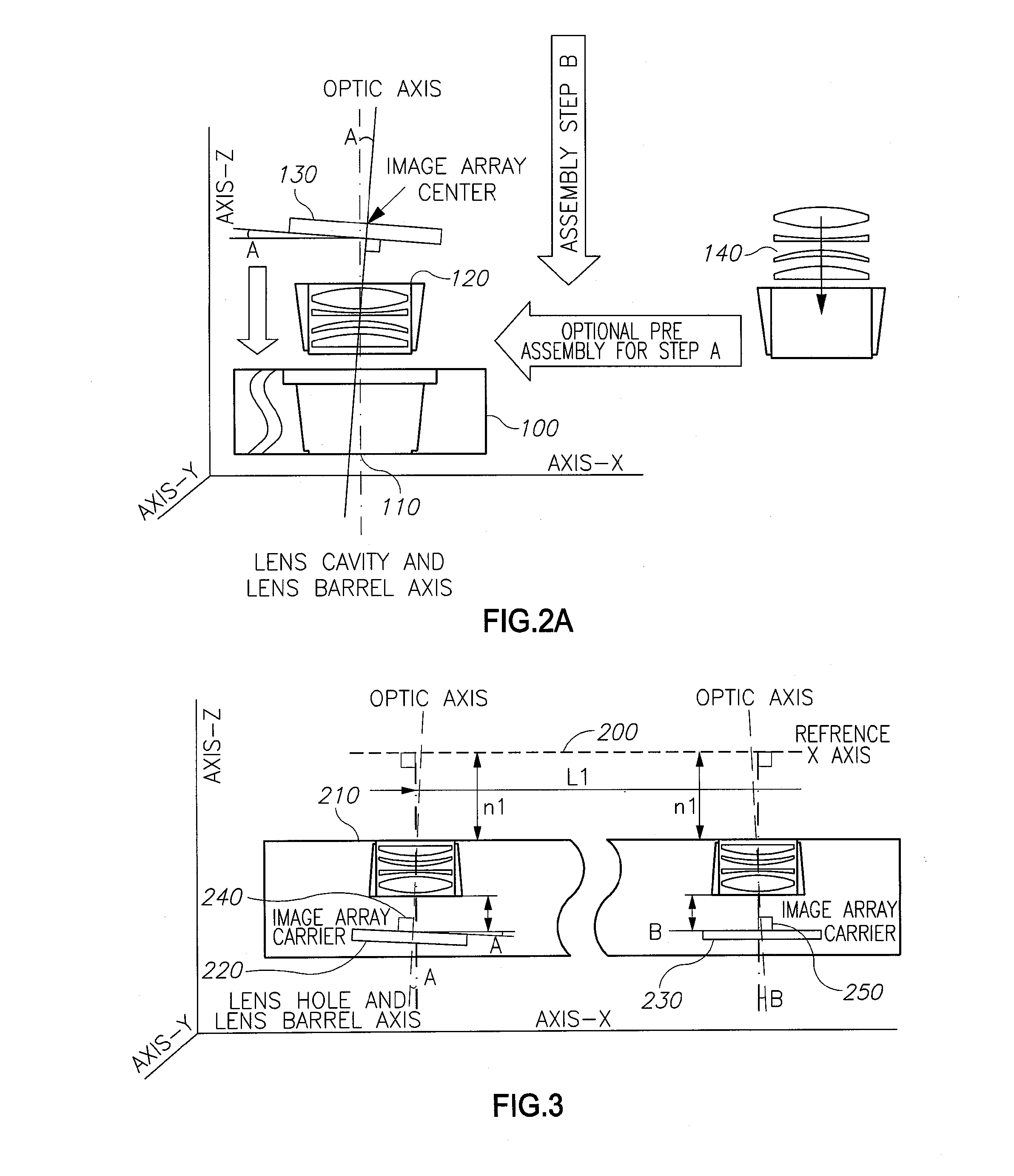
[0047]According to one embodiment of the present invention there is provided a system which includes an aligned stereoscopic assembly used for generating aligned stereoscopic images, such as, for example, from two or more video streams.

[0048]A stereo camera is an element comprises two camera units, assembled in a stereoscopic setup. In order to provide good results, the stereoscopic as...


PUM


Abstract

A stereoscopic optical assembly comprising: a single unit mounting bar having a plurality of openings for receiving a plurality of image capturing optical elements; a plurality of image capturing devices mounted on the single unit mounting bar; wherein the plurality of openings are arranged to enable obtaining a stereoscopic image from the plurality of image capturing devices, and wherein the stereoscopic image is derived from images captured by each of the image capturing devices.

Description

TECHNICAL FIELD[0001]The present disclosure generally relates to optical devices, and more particularly, to aligned stereoscopic assemblies.BACKGROUND[0002]A stereoscopic camera arrangement is an element made of two camera units, assembled in a stereoscopic module. Stereoscopy (also referred to as “stereoscopics” or “3D imaging”) is a technique for creating or enhancing the illusion of depth in an image by means of stereopsis. In other words, it is the impression of depth that is perceived when a scene is viewed with both eyes by someone with normal binocular vision which is responsible for creating two slightly different images of the scene in the two eyes due to the eyes'camera's different locations.[0003]Most stereoscopic methods present two offset images separately to the left and right image capturing means (the eyes of the viewer or cameras). These two-dimensional images are then combined to provide the perception of three dimensional depth. This technique is distinguished fro...

Claims


Application Information

Patent Timeline
Patent Type & Authority Applications(United States)
IPC IPC(8): H04N13/02G02B7/04G02B7/00H04N13/239
CPCG03B35/10G02B7/021H04N13/0239G02B7/04G02B7/003H04N2213/001H04N13/239
Inventor DOROT, SHAI
Owner INUITIVE
Why Eureka
Try Eureka