
Pump with Electric Motor

a technology of electric motors and rotors, applied in the direction of dynamo-electric components, dynamo-electric machines, magnetic circuit shapes/forms/construction, etc., can solve the problems of affecting the entire magnet, strong corrosion processes, etc., and achieve no negative corrosion effects, simplify the exact assembly of the rotor, and prolong the service life of the rotor significant

Active Publication Date: 2016-08-18
OASE GMBH
View PDF7 Cites 0 Cited by
  • Summary
  • Abstract
  • Description
  • Claims
  • Application Information

AI Technical Summary

Benefits of technology

The invention provides a pump with a balancing element on the rotor end face, which extends its service life while requiring minimal material usage. Balancing bores can be introduced into a separate balancing element to prevent corrosion on the magnet. The rotor can also have centering elements for easier assembly and to save components.

Problems solved by technology

When, as is conventional for balancing the rotor, one or several bores are introduced into the magnet itself, strong corrosion processes will occur in these bores that may afflict the entire magnet.

Method used


Image

  • Pump with Electric Motor
  • Pump with Electric Motor
  • Pump with Electric Motor

Examples


Embodiment Construction

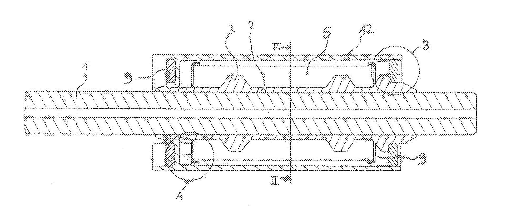
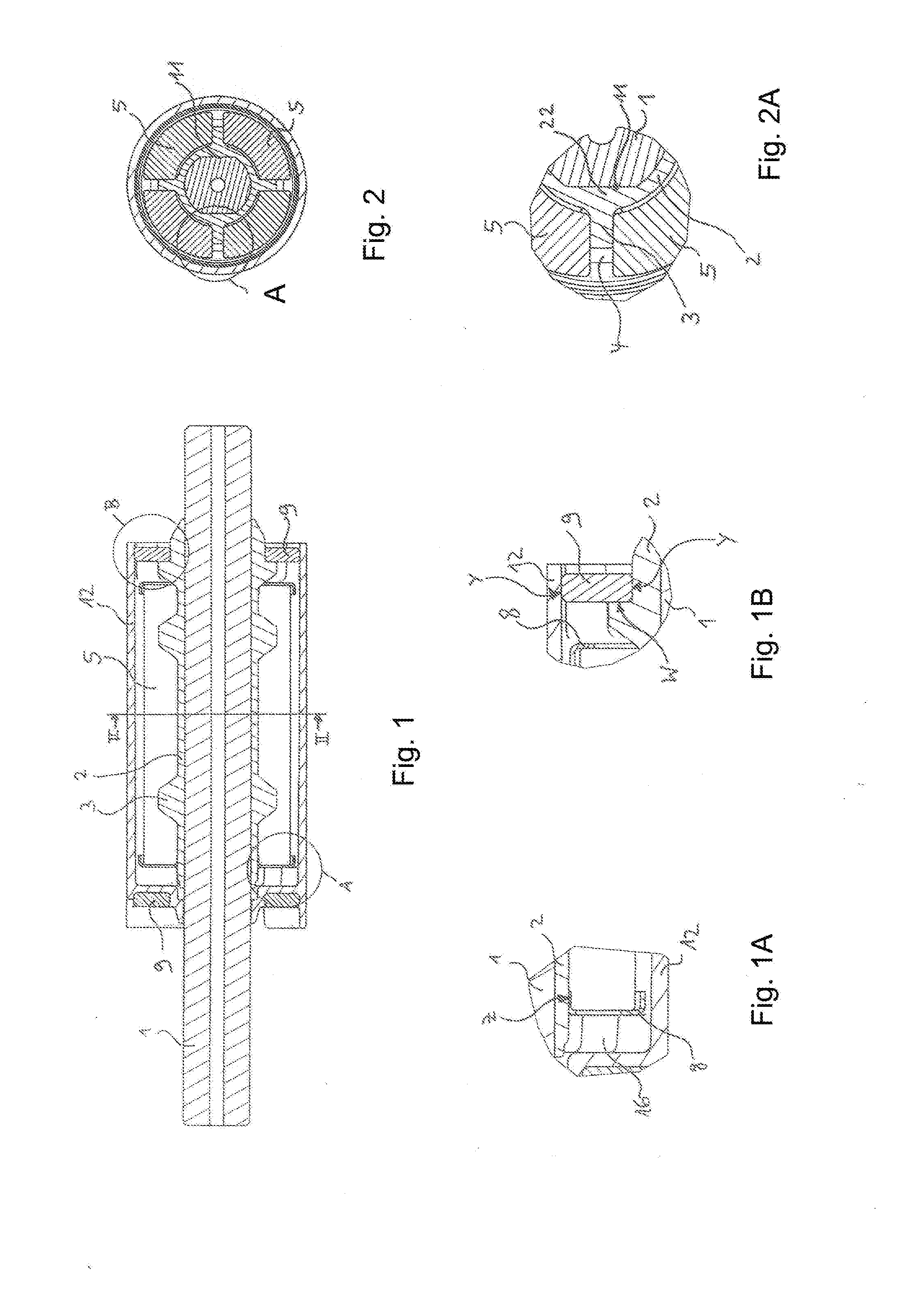
[0016]The rotor that is illustrated in FIGS. 1, 1A, 1B, 2, 2A, 4a, and 4b comprises a shaft 1 and a follower 2 that encloses the shaft 1, at least in some areas, like a sleeve. The follower 2 comprises projections 3 which, in the completely mounted state of the rotor, engage intermediate spaces that are formed between magnet segments 5.

[0017]The follower 2 is connected to the shaft 1 with form fit. In the illustrated embodiment, this is realized by lateral flat portions 11 (see FIG. 2) of the shaft 1 where wall sections of greater wall thickness 22 of the follower 2 are arranged that are matched precisely to the flat portions 11. By means of the projections 3 and the arrangement of magnet segments 5, the follower 2 is in turn connected with form fit to a magnet component group 6 that comprises the magnet segments 5 so that, indirectly, also a form-fit connection between the shaft 1 and the magnets 5, 6 is produced. The details can be seen in particular in FIG. 2A

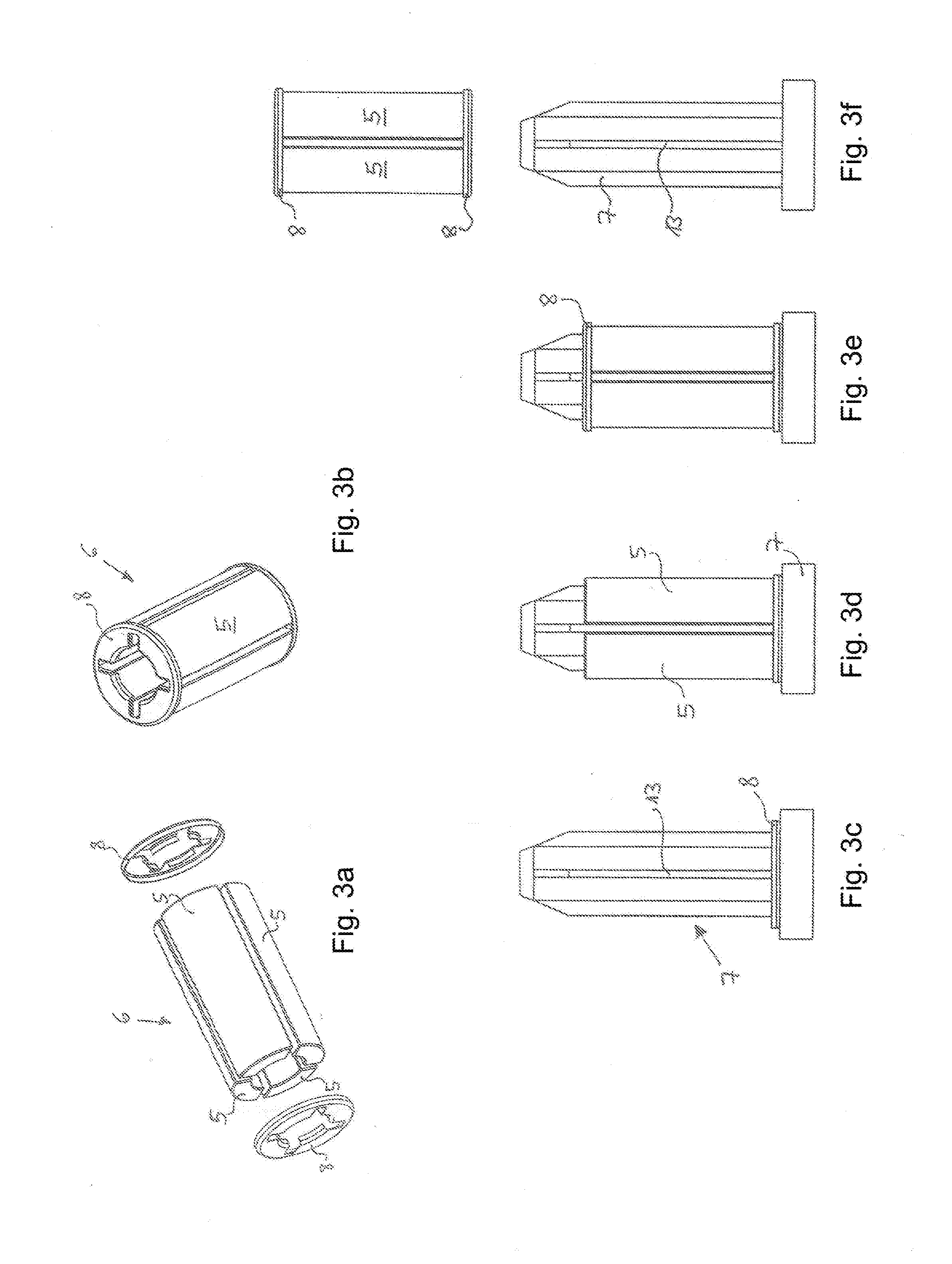
[0018]In FIGS. 3a to...


PUM


Abstract

A pump is provided with an electric motor that has a rotor. The rotor is provided with a shaft and a magnet surrounds the shaft. The magnet is connected with form fit to the shaft. A follower surrounds the shaft at least in some areas of the shaft. The follower is monolithically connected to the shaft or is connected with form fit to the shaft. The magnet is made of at least two magnet segments and the follower has projections which engage intermediate spaces formed between the magnet segments.

Description

BACKGROUND OF THE INVENTION[0001]The invention relates to a pump with electric motor, in particular a liquid pump, wherein the electric motor comprises a rotor comprising a shaft and a magnet surrounding the shaft.[0002]In pumps that, on the one hand, require a small size but, on the other hand, also a particularly high-performance electric motor, the rotor in practice is formed of a metal shaft or ceramic shaft and a magnet is pushed onto the shaft and then glued to the shaft. Usually, the shaft is subsequently embedded in plastic material. This configuration enables a very compact construction but the transmittable torque depends primarily on the selected adhesive connection. Also, the adhesive connections are partially subject to material fatigue so that the service life in regard to loadability is limited. In order to ensure the required connecting strength, the adhesive connection must therefore be of extremely high quality and is therefore very expensive.[0003]It is therefore ...

Claims


Application Information

Patent Timeline
Patent Type & Authority Applications(United States)
IPC IPC(8): H02K1/30H02K7/04H02K1/27
CPCH02K1/278H02K15/03H02K7/04H02K1/30H02K1/2706H02K1/276
Inventor LAMBERS, HERBERT
Owner OASE GMBH
Learn More