Transmission device and transmission method

Active Publication Date: 2016-08-11
SUN PATENT TRUST
View PDF2 Cites 0 Cited by
  • Summary
  • Abstract
  • Description
  • Claims
  • Application Information

AI Technical Summary

Benefits of technology

[0028]One non-limiting and exemplary embodiment provides a transmission device that can improve the degradation of the reception quality in the LOS

Problems solved by technology

However, depending on a transmission scheme (for example, a spatial multiplexing MIMO system), there occurs a problem that the reception quality degrades when the Rician factor increases.
Thus, it is clear that the problem in that “the reception quality degrades when the propagation environment is stabilized in the spatial multiplexing MIMO system”, which does not exist in the conventional single modulation signal transmission system, is generated in the spatial multiplexing MIMO system.
When the spatial multiplexing MIMO system is used in the broadcasting or multicast commu

Method used


Image

  • Transmission device and transmission method
  • Transmission device and transmission method
  • Transmission device and transmission method

Examples


first exemplary embodiment

[0121]A transmission method, a transmission device, a reception method, and a reception device according to a first exemplary embodiment will be described in detail.

[0122]Outlines of transmission and decoding methods in a conventional spatial multiplexing MIMO transmission system will be described prior to the description of the first exemplary embodiment.

[0123]FIG. 3 illustrates a configuration of an Nt×Nr spatial multiplexing MIMO system. Information vector z is subjected to encoding and interleaving. Encoded bit vector u=(u1, . . . , uNt) is acquired as interleaving output, where ui=(ui1, . . . uiM) (M is the number of transmission bits per symbol). Letting transmission vector s=(s1, . . . , sNt)T leads to transmission signal si=map(ui) from transmit antenna #i, and the normalized transmission energy is expressed by E{|si|2}=Es / Nt (Es is total energy per channel). Letting y=(y1, . . . , yNr)T expresses a received vector using Equation (1).

[Mathematicalformula1]y=(y1,…,yNr)T=HNtNr...

second exemplary embodiment

[0390]The transmission method, reception method, transmission device, and reception device in the case that the three streams are transmitted using the three antennas are described in the first exemplary embodiment.

[0391]A transmission method, a reception method, a transmission device, and a reception device in the case that four streams that can obtain the advantageous effect similar to that of the first exemplary embodiment are transmitted using four antennas will be described in a second exemplary embodiment.

[0392]FIG. 27 illustrates a configuration example of the transmission device of the second exemplary embodiment. In FIG. 27, the component operating similarly to FIG. 5 is designated by the identical reference mark. The transmission device in FIG. 27 differs from the transmission device in FIG. 5 in that fourth coded data exists. The operation of the component associated with the fourth coded data will be described below. (The operations of other component are similar to thos...

third exemplary embodiment

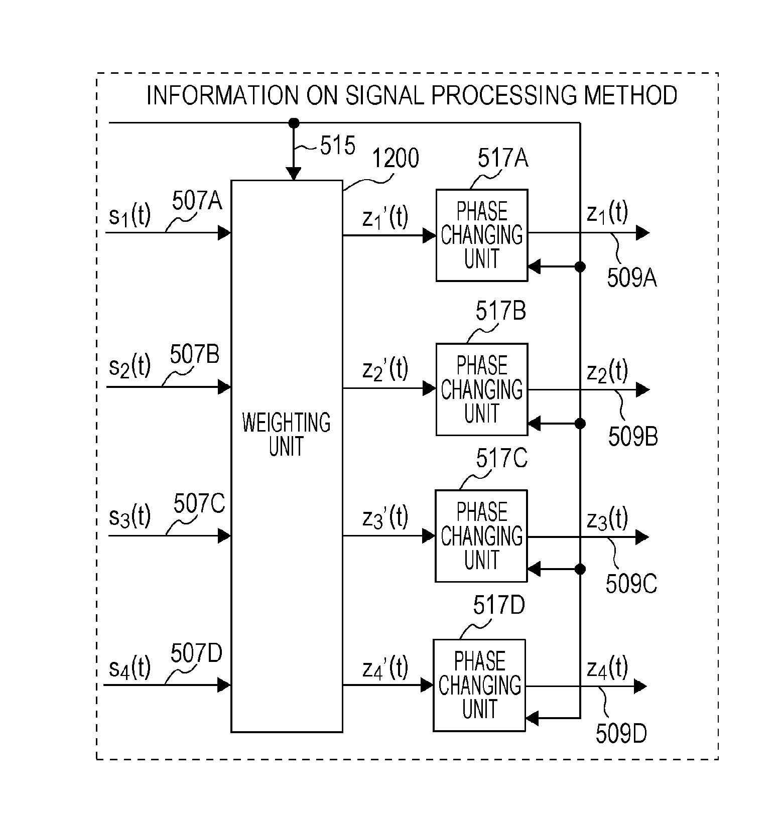
[0681]In the first and second exemplary embodiments, as illustrated in FIGS. 5, 6, 19, 20, 27, 28, 39, and 40, the mapping, the weighting, and the phase change are sequentially performed by way of example. A modification in which a phase changing unit or a power changing unit is added to the first and second exemplary embodiments will be described in a third exemplary embodiment. The phase changing method performed at a subsequent stage of the weighting may be operated similarly to the first and second exemplary embodiments.

[0682]The case that the four streams are transmitted using the four antennas are described in the third exemplary embodiment. In FIGS. 27, 28, 39, and 40, mapping unit 506A to phase changing unit 517A, mapping unit 506B to phase changing unit 517B, mapping unit 506C to phase changing unit 517C, and mapping unit 506D to phase changing unit 517D may be replaced with those in FIGS. 47, 48, 49, 50, 51, and 52. The operation in each drawings will be described below.

[0...


PUM


Abstract

A transmission device comprising: a weighting circuity which, in operation, generates transmission signals of n streams (n is an integer of 3 or more) by weighting modulated signals of the n streams using a predetermined fixed precoding matrix; a phase changing circuity which, in operation, regularly changes each phase of a symbol series included in each of the transmission signals of the n streams; and a transmitter which, in operation, transmits the transmission signals of the n streams from different antennas, the phases of each of the transmission signals of the n streams being changed in each symbol, wherein the transmission signal of an i-th stream has an mi kind of phase change value yi(t) (i is an integer between 1 and n (inclusive), 0≦yi<2π, and mi is set in each stream, t is an integer of 0 or more, and indicates a symbol slot), and the phase changing circuity changes the phase in one or more u (u=m1×m2× . . . ×mn) symbol periods using all patterns of a set of phase change values yi(t) different from each other in each symbol.

Description

BACKGROUND[0001]1. Technical Field[0002]The present disclosure relates to a transmission device and a reception device for conducting communication using a multi-antenna.[0003]2. Description of the Related Art[0004]Conventionally, for example, MIMO (Multiple-Input Multiple-Output) is well known as a communication method using a multi-antenna. In multi-antenna communication typified by MIMO, pieces of transmission data of a plurality of series are modulated, and each modulated signal is transmitted from a different antenna simultaneously to increase the transmission speed of data.[0005]FIG. 1 illustrates a configuration example of a transmission and reception device having two transmit antennas, two receive antennas, and two transmission modulated signals (two transmission streams). In the transmission device, encoded data is interleaved, the interleaved data is modulated, and frequency conversion and the like is performed to generate transmission signals, and the transmission signal...

Claims


Application Information

Patent Timeline
IPC IPC(8): H04B7/04H04B7/06
CPCH04B7/046H04B7/0682H04B7/0615H04B7/0456H04L1/005
Inventor MURAKAMI, YUTAKAKIMURA, TOMOHIROOUCHI, MIKIHIRO
Owner SUN PATENT TRUST
Why Eureka
Try Eureka