
Drill rod for percussion drill tool

Active Publication Date: 2016-08-11
MINCON INT
View PDF8 Cites 3 Cited by
  • Summary
  • Abstract
  • Description
  • Claims
  • Application Information

AI Technical Summary

Benefits of technology

[0045]Preferably, a face seal is provided in at least one of the first and second planar end faces, to effect a seal with the opposing end face. A face seal is a seal in which the sealing surfaces are normal to the axis of the seal, that is, it effects a seal by interacting primarily in a longitudinal or axial direction between the first and second end faces. The face seal may be provided in an annular recess on the first or second planar end face. The face seal may encircle at least one of the outlet for press

Problems solved by technology

However, such pneumatically powered hammers are energy inefficient and often suffer performance constraints, especially when drilling small diameter holes.
However, there are a number of disadvantages of open circuit designs, even those that are liquid powered.
A first disadvantage is that there is no independent control of the flushing flow rate vs. the percussion mechanism flow rate.
Whenever there is a large variance between the two requirements, energy will be wasted and/or hammer performance will be compromised.
Another disadvantage is that the choice of fluid to drive the hammer is limited to those that are suitable for both driving the percussion mechanism and flushing the hole.
This almost always results in the use of a fluid that is not optimal for either purpose.
However, for obvious environmental and economic reasons, it is not suitable for flushing the drilled hole.
On the other hand, water may be suitable for flushing the hole, but is generally a poor choice for use in the percussion mechanism.
A further disadvantage of open circuit systems is that the fluid chosen to drive the hammer must be available in large quantities, or must be recycled once it exits the drilled hole.
This is a significant disadvantage for many drilling applications, since either the drill rig must be connected to an adequate supply of fresh fluid or it must utilise a complicated fluid capture and filtration system.
In most situations, both are required, significantly reducing the mobility of such rigs.
However, despite their advantages, closed circuit liquid-powered hammers have not found

Method used


Image

  • Drill rod for percussion drill tool
  • Drill rod for percussion drill tool
  • Drill rod for percussion drill tool

Examples


Example

DETAILED DESCRIPTION OF THE DRAWINGS

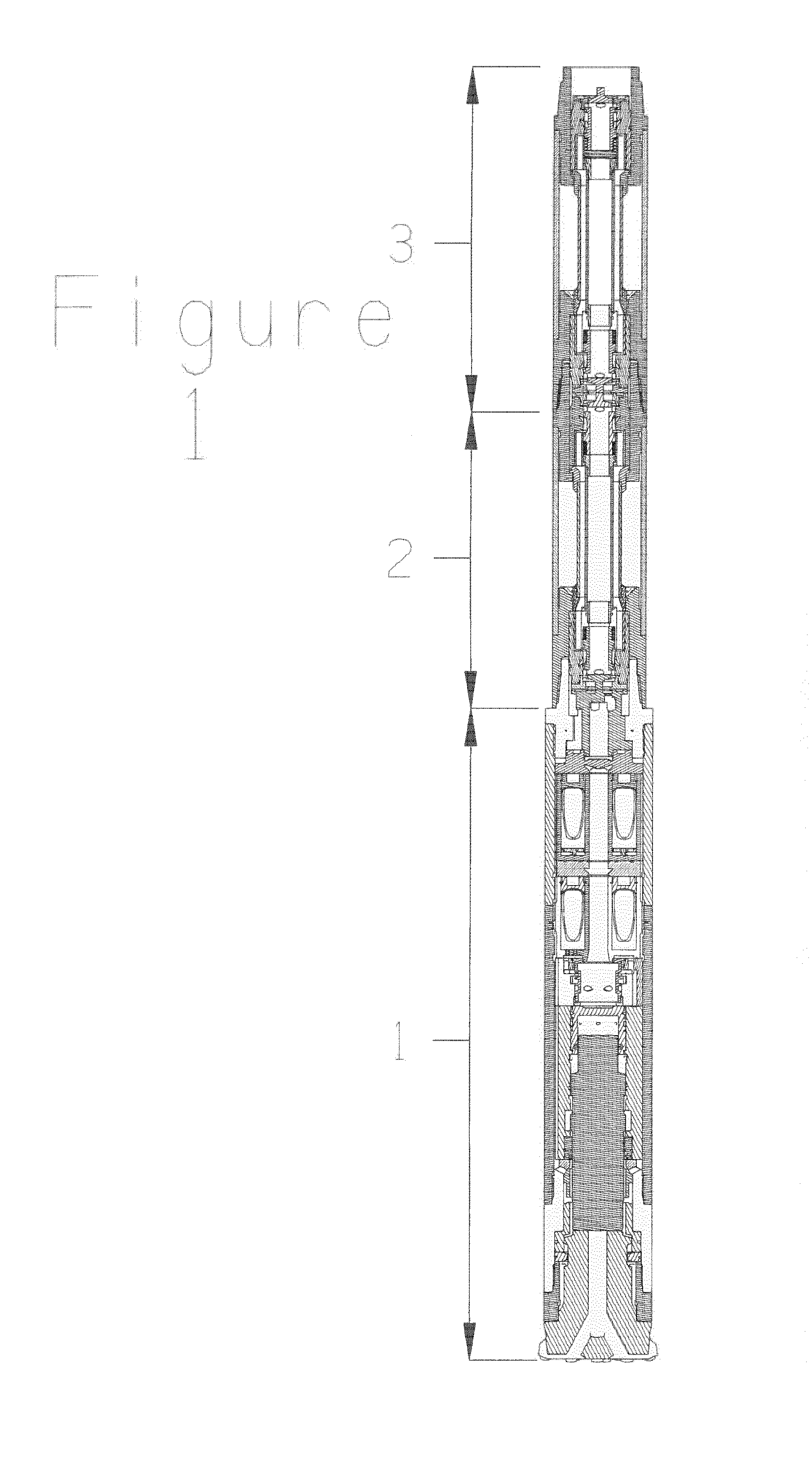
[0065]A hydraulic down-the-hole drilling system incorporating two drill rods 2, 3 according to the present invention is shown in FIG. 1. The system includes a hammer 1, which is fed pressure fluid and flushing fluid and which discharges return fluid through drill rods 2, 3.

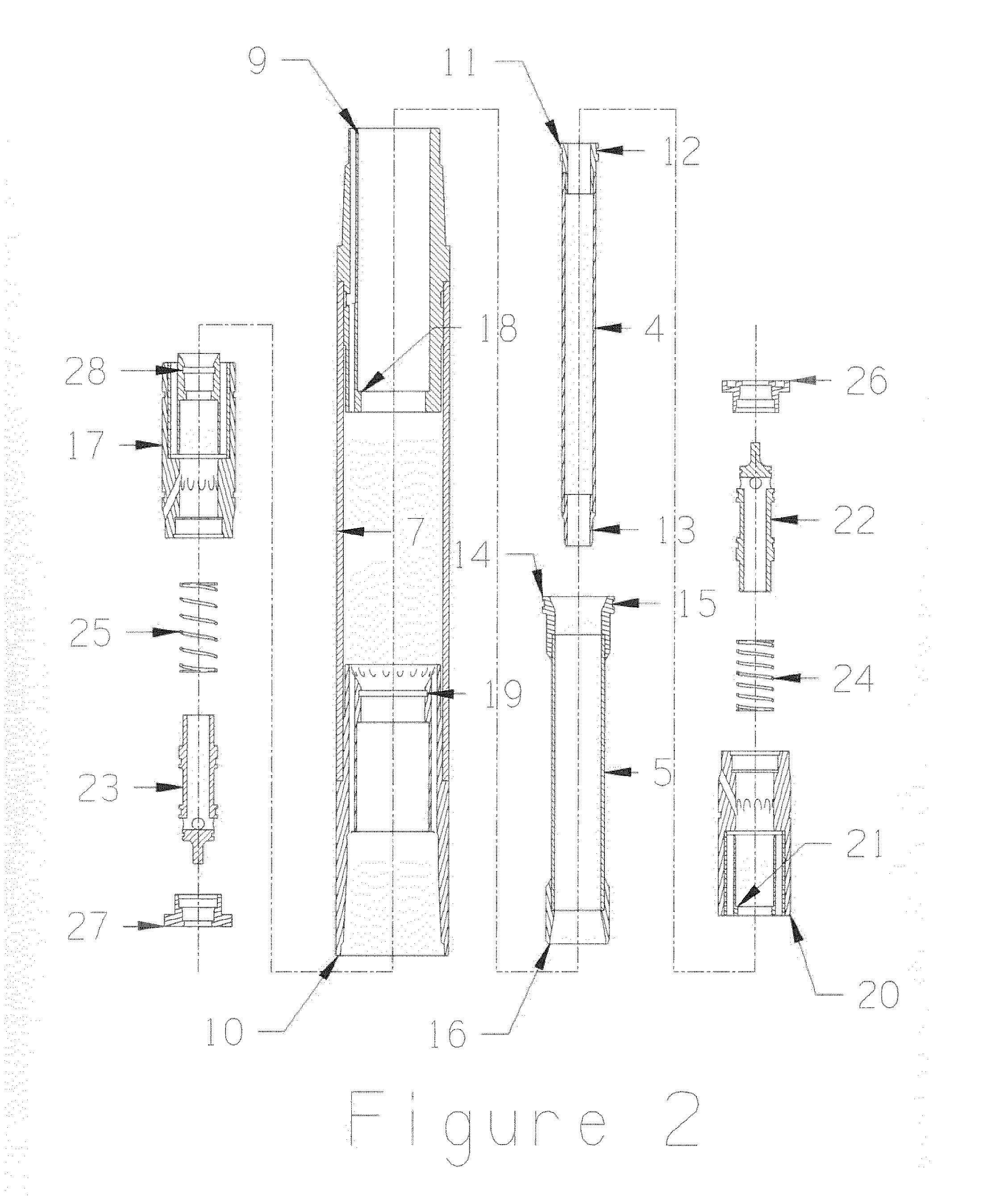
[0066]FIGS. 2 and 3 show a drill rod 2 according to an embodiment of the present invention. The drill rod 2 has a female connection interface 100 at a first end 101 and a male connection interface 102 at a second end 103. The female connection interface 100 is for connection of the drill rod 2 to a male connection interface 102 of a like drill rod 3 or to the hammer 1, as shown in FIG. 1. The drill rod 2 has a plurality of discrete fluid flow channels 4, 6, 8 provided by a concentric tube structure. The drill rod comprises a centre tube 4, which carries pressure fluid, and which is surrounded by middle tube 5. Return fluid is carried in an annular channel 6 between centre tube 4...


PUM


Abstract

The present invention relates to a drill rod (2) for a fluid-operated apparatus, particularly a percussion drill tool (1). The drill rod (2) comprises a first connection interface (100) at a first end (101) and a second connection interface (102) at a second end (103). The first connection interface (100) is for connection of the drill rod (2) to a second connection interface (102) of a like drill rod (3) or to the apparatus (1). The second connection interface (102) is for connection of the drill rod (2) to a first connection interface of a like drill rod (3) or to a fluid transfer device. The drill rod also comprises a plurality of discrete fluid flow channels (4, 6, 8) through the drill rod, a first member (23) moveably mounted in the first connection interface (100) and a second member (22) moveably mounted in the second connection interface. The first moveable member is the innermost component in the first connection interface and the second moveable member is the innermost component in the second connection interface. When the drill rod (2) is connected to a like drill rod (3) or to the apparatus (1) or to the fluid transfer device, at least two of the fluid flow channels (4, 6) are placed in fluid communication with corresponding channels (4, 6) of the like drill rod or the apparatus or the fluid transfer device by movement of the first (23) and second (22) moveable members only.

Description

FIELD OF THE INVENTION[0001]The present invention relates to fluid-powered apparatus such as percussion drill tools, including down-the-hole hammers, and, in particular, to drill rods for liquid-powered down-the-hole hammers.BACKGROUND TO THE INVENTION[0002]The drilling of holes in high-strength rock using down-the-hole (DTH) percussive hammers is a well-established technique. There are a variety of such hammers in common use, for a wide variety of drilling applications. Virtually all of these commonly used hammers are of an “open circuit” design, in which a pressurised fluid is used to transmit energy to the hammer and then the same fluid, once it has been exhausted from the percussion mechanism, is used to flush the drill cuttings from the hole being drilled. Air is the most commonly used fluid in such hammers, and, in most cases, is a very suitable flushing medium. However, such pneumatically powered hammers are energy inefficient and often suffer performance constraints, especia...

Claims


Application Information

Patent Timeline
IPC IPC(8): E21B21/12E21B1/00E21B17/18E21B17/042E21B17/07
CPCE21B21/12E21B4/14E21B17/0426E21B17/07E21B21/10E21B1/00E21B17/042E21B17/18E21B17/02E21B17/04F16L39/005
Inventor PURCELL, JOSEPHKOSOVICH, JOHNWANG, TONY
Owner MINCON INT
Learn More