Supercharge Your Innovation With Domain-Expert AI Agents!
Hydraulic fluid compositions
Active Publication Date: 2016-07-21
HOUGHTON TECH CORP
View PDF4 Cites 7 Cited by
Summary
Abstract
Description
Claims
Application Information
AI Technical Summary
This helps you quickly interpret patents by identifying the three key elements:
Problems solved by technology
Method used
Benefits of technology
Benefits of technology
[0009]In another aspect, a method for preventing uncontrolled flow of gas, oil, or another well fluid out of an underground formation during a dr
Problems solved by technology
A blowout can occur when formation pressure exceeds the pressure applied to it by the drilling or extraction apparatus.
There are several challenges for the fluid which delivers the hydraulic pressure.
For example, use of conventional hydraulic fluids can be complicated by low flash points and poor fire resistance.
Also, toxicity, bioaccumulation, and biode
Method used
Image
Click on the blue label to locate the original text in one second.
Reading with bidirectional positioning of images and text.
Examples
example 1
[0103]A hydraulic fluid composition described herein was prepared and contained the components, all of which are available from commercial vendors, of Table 1.
TABLE 1ComponentAmount (%)water60.35monoethanolamine8triethanolamine2mixture of C3 to C13 dicarboxylic acids39-octadecenoic acid (9Z), sulfurized30.1oleyl alcohol, ethoxylated, phosphate2.5triazine6ethylene glycol15dye0.05
[0104]The sea water stability (ASTM D1141 procedure), falex coefficient of friction (modified ASTM D3233-B procedure), falex breakdown load (modified ASTM D3233-B procedure), falex wear @1000 pounds (modified API 17F standard), 4 ball wear test (ASTM D2783-88 procedure), piston pump wear (Vickers PFB 5 pump), and Cefas rating (offshore chemical notification scheme—OCNS) were estimated using the noted standard techniques for the composition of Table 1 and the composition of Stack-Magic ECO-Fv2. The results are shown Table 2.
TABLE 2Stack-MagicInstantPropertyECO-Fv2CompositionSea Water StabilityorangegreenFalex ...
example 2
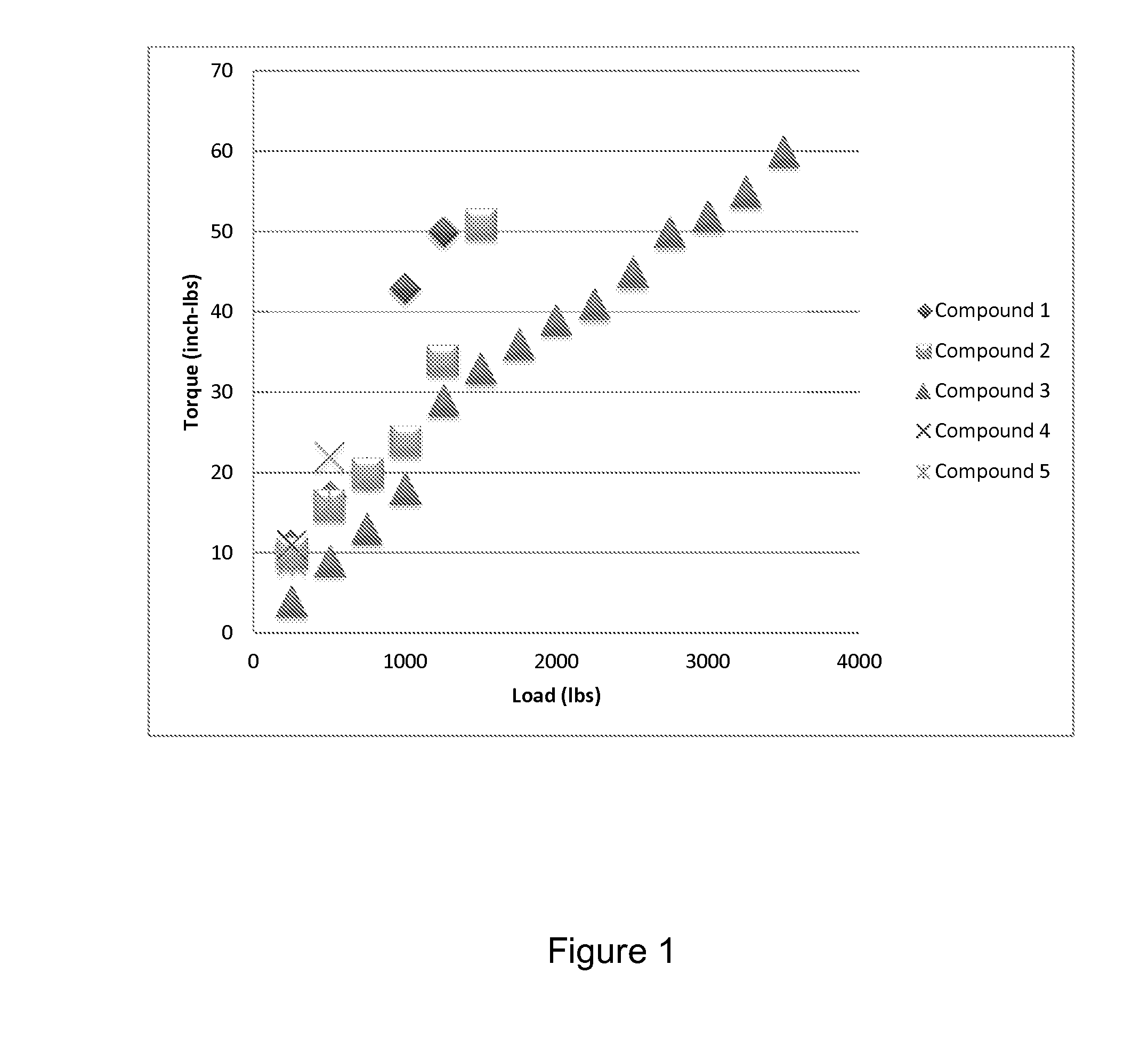
[0106]Five formulations were prepared which all contain the same corrosion inhibitors, biocide components, ethylene glycol, and water (base formulation), deviating from each other only in the concentration of phosphate ester of ethoxylated oleyl alcohol and sulfurized oleic acid according to Table 3. All of these components are commercially available.
[0107]The load was applied according to ASTM D3233 standard testing and the torque determined for each composition and the results are provided in Table 4. A plot of the load vs. torque was generated (FIG. 1) and the coefficients of friction determined form the slopes.
[0108]The data illustrates that the highest loads a...
PUM
Abstract
A novel hydraulic fluid composition for application to drilling equipment is described herein. These hydraulic fluid compositions permit effective monitoring or controlling well-head pressure of a well during drilling on land or offshore. The hydraulic fluid compositions prevent uncontrolled flow of gas, oil, or another well fluid out of an underground formation during a drilling or extraction process when applied to the drilling equipment. Accordingly, provided is a hydraulic fluid concentrate which contains a water-soluble phosphate ester and a sulfide compound containing at least one S—S linkage, at least 10 carbon atoms and at least one terminal carboxylate group, wherein the S—S linkage bridges two alkyl groups. Additional components can be added to the concentrate and include one or more alkaline compound, one or more dicarboxylic acid or salt thereof, a water-soluble corrosion inhibitor, a water-soluble biocide, a pour point depressant, and water, ethylene glycol, or a combination thereof. The concentrate is then further diluted by the customer for use as described herein. Particularly, these compositions are effective in reducing seawater corrosion of a metal in contact with the hydraulic fluid composition, reducing bioaccumulation in oil drilling equipment contacted with the hydraulic fluid composition, and have low toxicity to sea life.
Description
BACKGROUND OF THE INVENTION[0001]Hydraulic fluids are usable in blowout preventer (BOP) devices to control well-head pressure of a well that is being drilled and / or in marine environments. A “blowout” is defined as uncontrolled flow of gas, oil, or other well fluids out of an underground formation. A blowout can occur when formation pressure exceeds the pressure applied to it by the drilling or extraction apparatus. A BOP is a specialized valve, usually installed redundantly, in series, to seal, control and monitor oil and gas wells. The BOP is actuated by hydraulic pressure that forms a seal around the drill string to seal off well head pressure when an area of high pressure has been contacted.[0002]There are several challenges for the fluid which delivers the hydraulic pressure. For example, use of conventional hydraulic fluids can be complicated by low flash points and poor fire resistance. Also, toxicity, bioaccumulation, and biodegradation of conventional fluids can lead to env...
Claims
Application Information
Patent Timeline
Application Date:The date an application was filed.
Publication Date:The date a patent or application was officially published.
First Publication Date:The earliest publication date of a patent with the same application number.
Issue Date:Publication date of the patent grant document.
PCT Entry Date:The Entry date of PCT National Phase.
Estimated Expiry Date:The statutory expiry date of a patent right according to the Patent Law, and it is the longest term of protection that the patent right can achieve without the termination of the patent right due to other reasons(Term extension factor has been taken into account ).
Invalid Date:Actual expiry date is based on effective date or publication date of legal transaction data of invalid patent.
