
Trash collector

a technology for trash bags and collectors, applied in the field of trash collectors, can solve the problems of slipping of trash bags, significantly higher material costs, and increased material costs, and achieve the effect of preventing any slippage of trash bags

Inactive Publication Date: 2016-07-14
ROTHO KUNST
View PDF4 Cites 32 Cited by
  • Summary
  • Abstract
  • Description
  • Claims
  • Application Information

AI Technical Summary

Benefits of technology

The present invention relates to a trash collector with a lid that can be opened without needing to remove the entire lid. The lid can be opened to a limited angle, allowing for easy handling of the trash bag or the removal of a separate bucket. The trash collector also has removable spring bars to secure the trash bag and prevent it from slipping into the bucket. The technical effects of this invention include improved convenience and efficiency in trash collection.

Problems solved by technology

Trash collectors of the prior art with a lid, pivotal upon a pedal being pressed, have the problem that with increasing volume of the trash collector and accordingly increasing lid area the lid becomes heavier and heavier and thus the lever arrangement must transfer appropriately large forces.
For reasons of cost efficiency it is however not advantageous to embody the trash collector with a double wall, thus providing an encasement, which receives a separately removable bucket, particularly since in a large volume trash collector the bucket generally must be lined by the user with a trash bag, which can be removed from the bucket for discarding the collected trash.
In particular in case of a cost-effective production of the trash collector from plastic, particularly preferred within the scope of the present invention, the double-walled embodiment leads to significantly higher material costs as well as the need for a separate production of the individual parts, with corresponding higher expenses.

Method used


Image

  • Trash collector
  • Trash collector
  • Trash collector

Examples


Embodiment Construction

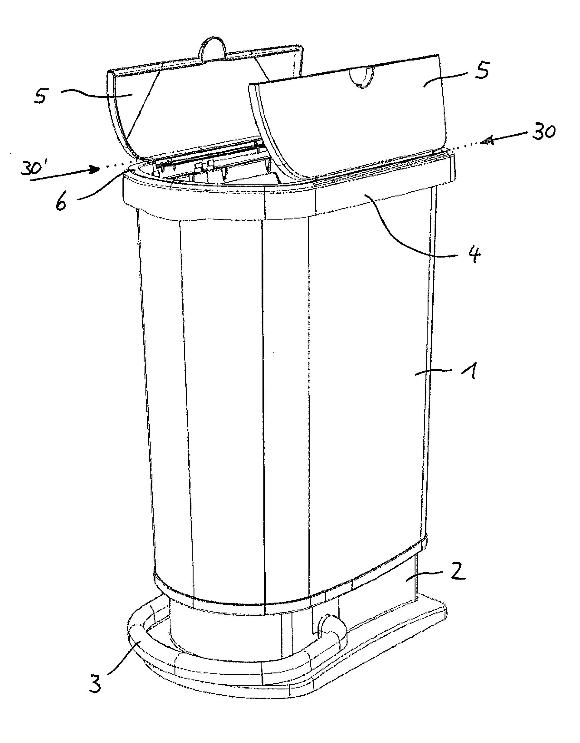
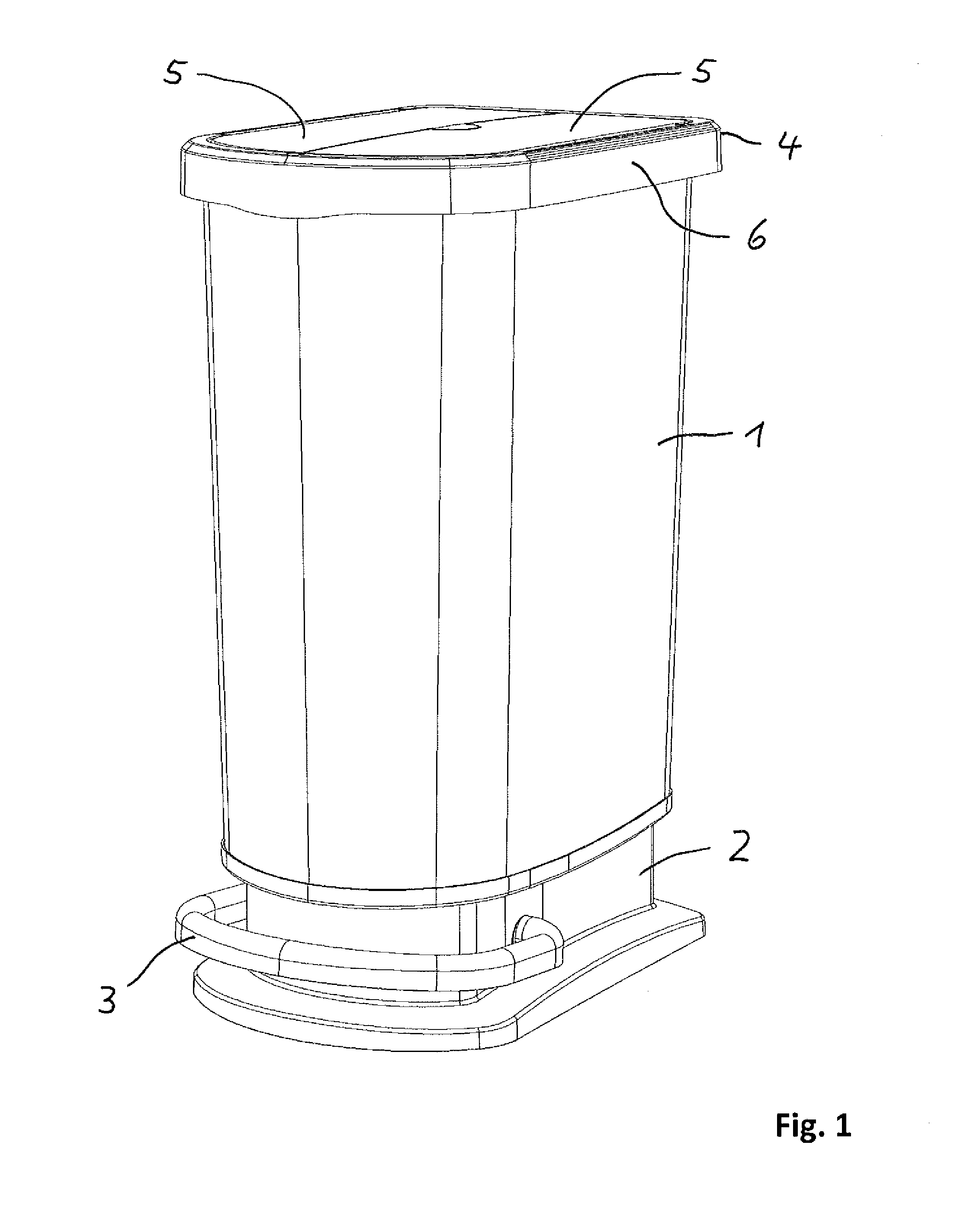
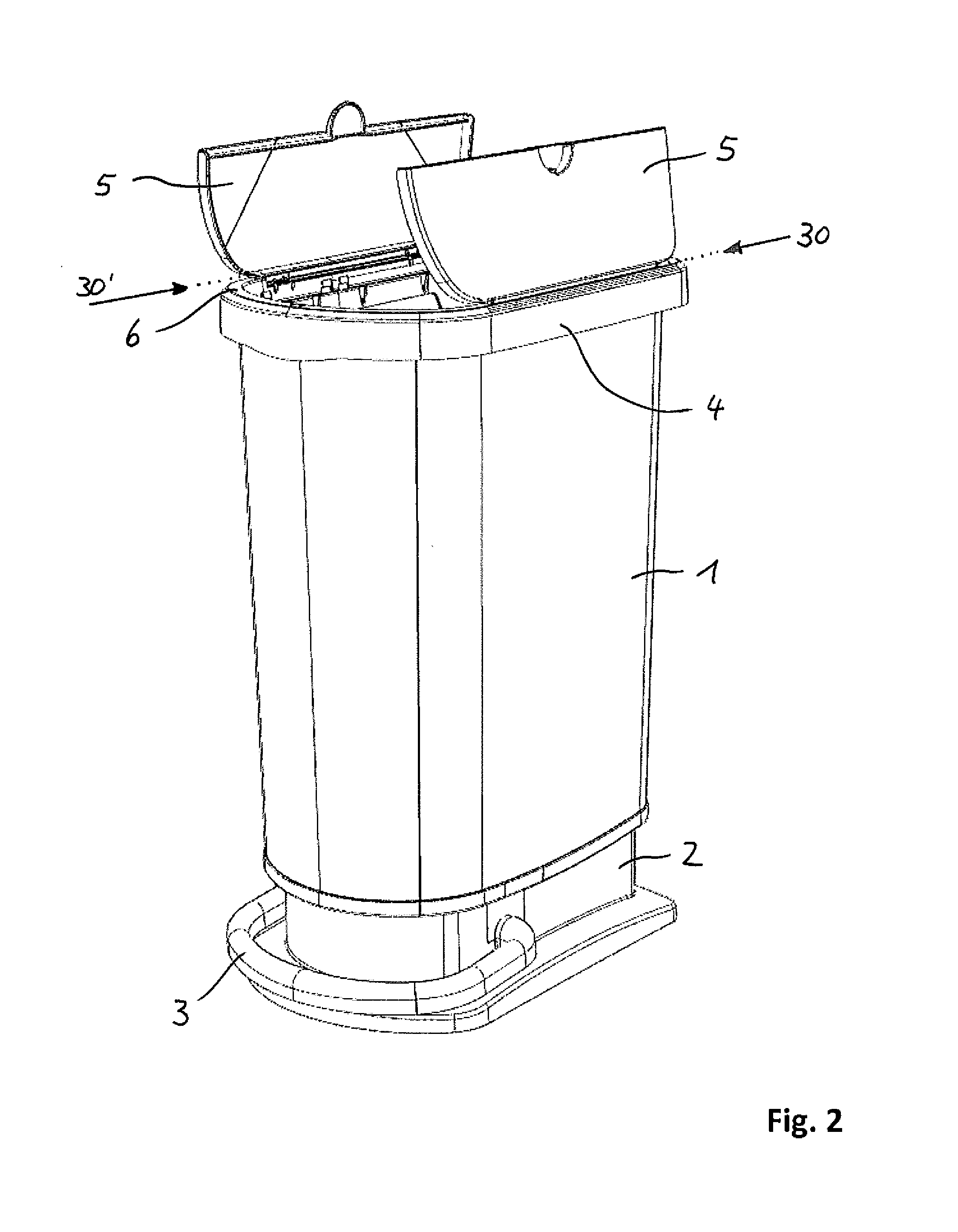
[0039]The trash collector shown in FIGS. 1 to 3 in a closed state (FIG. 1), opened state (FIG. 2), and / or completely opened state (FIG. 3) in a comprehensive view comprises a bucket 1, which simultaneously forms the exterior casing of the trash collector, a base part 2 with a pedal 3, as well as a lid 4, having two lid sections 5, which cover the bucket 1 and are fastened in a pivotal fashion to a frame element 6 formed as an annular fitting.

[0040]FIG. 1 shows the trash collector in the completely closed state. The frame element 6 rests on the upper brim of the bucket 1 and the lid sections 5 are closed, so that these three components forming the lid 4 completely cover the top of the bucket 1 in its entirety.

[0041]By actuating the pedal 3 the lid sections 5 are pivoted open, as illustrated in FIG. 2. Each of the two lid sections 5 is fastened to the frame element 6, pivotal by a separate hinge, with the pivotal axes 30, 30′ about which the two lid sections 5 are pivoted open, that a...


PUM


Abstract

A trash collector, including a bucket 1 and a lid 4, which covers the bucket and is fastened pivotally in the area of an upper brim of the bucket, in order to pivot it upwards to open the trash collector. A pedal arrangement 3, 20 is arranged in the area of a base of the bucket, and a lever arrangement 8, 12 connects the pedal arrangement to the lid in order to pivot open the lid by a motion of the pedal arrangement. The lid is embodied in several parts and has at least two lid sections 5, which are each pivotable about as separate axis 30, 30′, and a frame element 6, which is provided detachably and / or pivotally in the area of the upper brim of the bucket and to which the lid sections 5 are fastened in a pivotal fashion.

Description

[0001]INCORPORATION BY REFERENCE[0002]The following documents are incorporated herein by reference as if fully set forth: European Patent Application No. EP 15 150 519.5, filed Jan. 8, 2015.BACKGROUND[0003]The present invention relates to a trash collector. Such a trash collector comprises a bucket and a lid as well as a pedal arrangement and a lever arrangement. The lid covers the bucket and is fastened in a pivotal fashion in the area of the upper brim of the bucket in order to pivot it upwards to open the trash collector. The pedal arrangement is arranged near the bottom of the bucket and is connected via the lever arrangement to the lid, in order to pivot the lid by a motion of the pedal arrangement.[0004]Trash collectors of this type have been known for quite some time in various embodiments. By stepping onto the pedal the lid is pivoted upwards via the lever arrangement in order to open the trash collector. Upon release of the pedal the lid flips downwards automatically, usual...

Claims


Application Information

Patent Timeline
Patent Type & Authority Applications(United States)
IPC IPC(8): B65F1/14B65F1/06
CPCB65F1/163B65F2001/1669B65F1/1646B65F1/06B65F2001/1661
Inventor THOMA, CHRISTIANMEIER, BRUNO
Owner ROTHO KUNST
Learn More