
Electron Microscope

a technology of electron microscope and optical system, applied in the field of electron microscope, can solve the problems of inability to observe in real time, inability to substantially achieve real-time observation or the like, and small period of time taken for spreading methods, so as to improve the accuracy of optical system adjustment, shorten the time required for readjusting the optical system, and reduce the burden of electron microscope operators

Active Publication Date: 2016-07-07
HITACHI HIGH-TECH CORP
View PDF8 Cites 11 Cited by
  • Summary
  • Abstract
  • Description
  • Claims
  • Application Information

AI Technical Summary

Benefits of technology

The present invention simplifies the execution of the lens-less Foucault method, reducing the time and effort required for readjusting the optical system and improving the accuracy and reproducibility of the experiment. This method allows for easier observation of plural images and improves the accuracy and reliability of the experiment.

Problems solved by technology

That is, observations at plural times are needed, and a dynamic observation, a real time observation or the like has substantially been impossible.
Therefore, it seems that a small period of time is taken for spreading the method.
Although any of the methods have respective advantages, it is an actual situation that there are a number of complications in implementing the methods such that an electron beam having a high coherence of an electric field emission type electron beam is needed, an electron beam biprism is needed as an additional device in the electron beam holography, a domain for transmitting a reference wave needs to be considered in a sample shape, at least 2 sheets of images defocusing amounts of which are already known are needed by interposing an image in focus (a total of three sheets of images) in the intensity transportation equation method, and magnifications and an adjusting process of positioning or the like for respective images are indispensable and so on.

Method used


Image

  • Electron Microscope
  • Electron Microscope
  • Electron Microscope

Examples


first embodiment

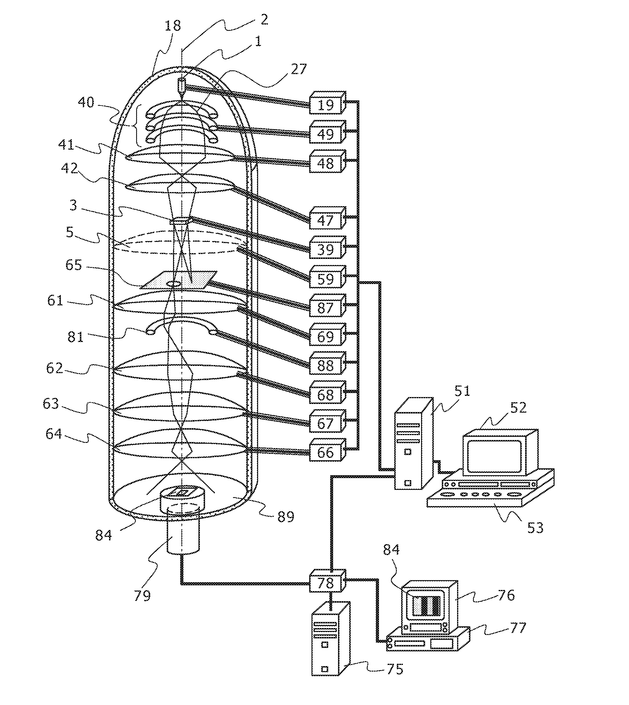
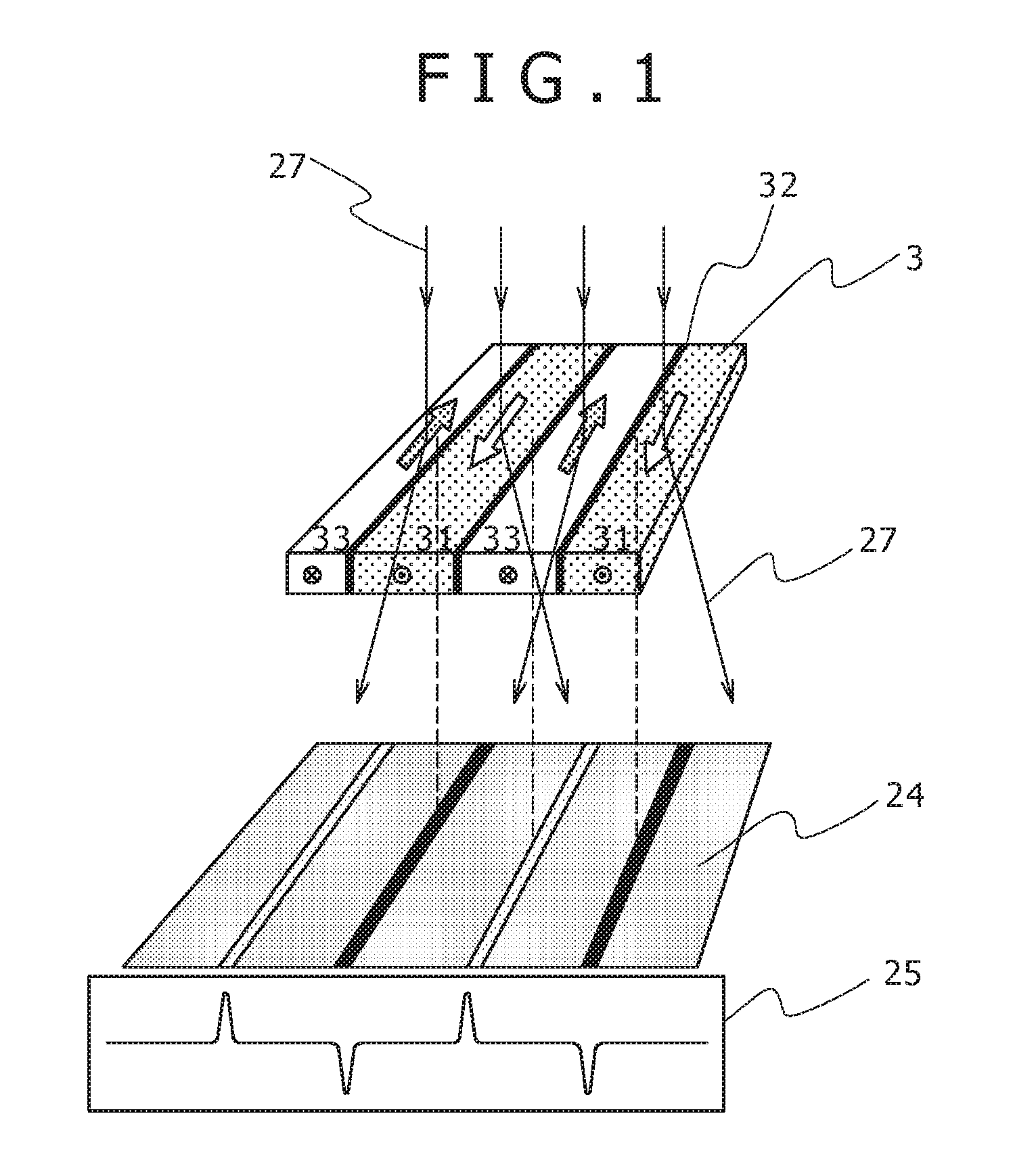
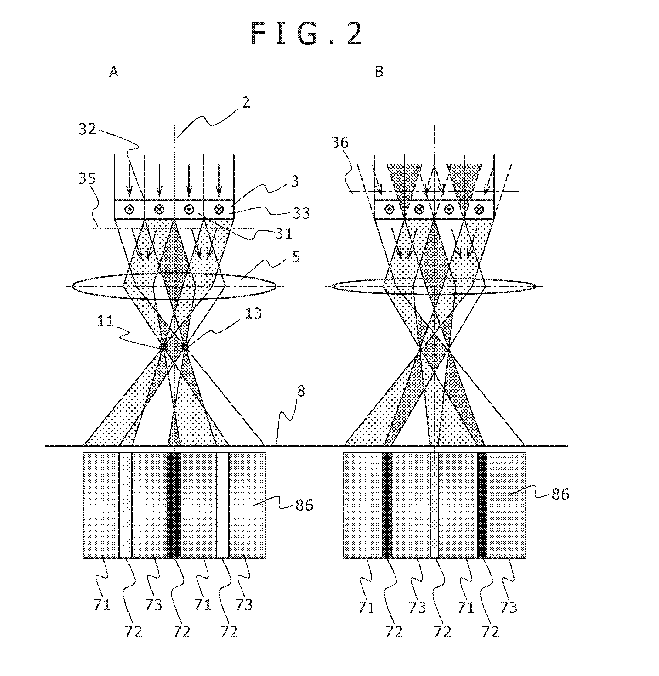
[0058]The present invention relates to a method of realizing a Foucault method in a general use type transmission electron microscope which does not include an attachment device for observing a magnetic domain structure (for example, a magnetic shielding lens or the like), and it is a method in which in place of the objective lens turning off a current for excluding an influence of a magnetic field on a sample, a crossover is focused at a selected area aperture position by an irradiating optical system, an electron beam receiving a magnetic deflection is selected to adopt or abandon by the aperture, and focused and observed as a Foucault image by a focusing optical system at a later stage. A small angle diffraction pattern observation of the electron beam receiving the deflection and the Foucault image observation are realized by changing a focal length of the first imaging lens below the objective lens, and a deviation of an optical axis at this occasion is corrected by a deflector...

second embodiment

[0068]FIG. 8 shows an example of a control panel of a control system used in the present invention. Ordinarily, a sample inching knob (horizontal two directions of X direction and Y direction: 531X, 531Y), an amplification adjusting knob 532, an irradiating area adjusting knob 533, an irradiating system deflection adjusting knob 534, a focus adjusting knob 535 and the like are arranged on the control panel 53. These are often used in operating an electron microscope, and even in an electron microscope controlled by the control system computer, these are installed on the control panel for reducing a burden of an operation of an operator.

[0069]In addition to the knobs or the like described above, the control panel 53 according to the present invention is added with adjustment stopping means 539 of the irradiating optical system and stop release operating means 538 thereof. In the lens-less Foucault method, as described above, crossovers need to be focused at a position of a aperture o...

third embodiment

[0071]FIG. 9 shows an example of the control panel 53 of the control system used in the present invention which is different from that of the second embodiment. A shape of the control panel 53, the control knobs and the like including the adjustment stopping means 539 and the stop release operating means 538 of the irradiating optical system (531X, 531Y, 532, 533, 534, 535) are similar to those of FIG. 8. In addition thereto, in FIG. 9, there is drawn a behavior of adding a switching knob of an observation mode on the control panel 53. On the control panel 53 of a conventional electron microscope, there are provided means (successively, 527, 528, 529) for constructing optical systems in accordance with respective objects of observation such as an image observation mode, a low amplification image observation mode, a diffraction pattern observation mode and the like by a simple operation.

[0072]In addition to the knob and the like as described above, in the control panel 53 of the pres...


PUM


Abstract

The present invention relates to a lens-less Foucault method wherein a transmission electron microscope objective lens (5) is turned off, an electron beam crossover (11, 13) is matched with a selected area aperture (65), and the focal distance of a first imaging lens (61) can be changed to enable switching between a sample image observation mode and a sample diffraction pattern observation mode, characterized in that a deflector (81) is disposed in a stage following the first imaging lens (61), and conditions for an irradiating optical system (4) can be fixed after conditions for the imaging optical system have been determined. This allows a lens-less Foucault method to be implemented in a common general-use transmission electron microscope with no magnetic shielding lens equipped, without burdening the operator.

Description

TECHNICAL FIELD[0001]The present invention relates to an electron microscope, and a sample observation method using the electron microscope.BACKGROUND ART[0002]A Lorenz microscope method has been developed as a method of observing a behavior of deflecting an electron beam transmitting a magnetic material by receiving a Lorenz force by magnetizing a sample as its name signifies. However, currently, the method is received as a method of visualizing a deflection state of an electron beam, or a method of visualizing an electron beam receiving a deflection by an interactive operation different from Bragg diffraction caused by a crystal structure not only for the magnetic material but a dielectric polarization, a strain field or the like. Roughly classified, there are two methods of a Foucault method and a Fresnel method in the Lorenz method (Nonpatent Literature 1), in term of the magnetic material, the Fresnel method is a method of observing a domain wall, and the Foucault method is a m...

Claims


Application Information

Patent Timeline
Patent Type & Authority Applications(United States)
IPC IPC(8): H01J37/10H01J37/147H01J37/05H01J37/285
CPCH01J37/10H01J37/285H01J2237/21H01J37/05H01J37/1472H01J37/295H01J37/04H01J37/261H01J2237/2614G01N23/20058G01N2223/418H01J37/09H01J37/147H01J37/153H01J37/24H01J37/244H01J37/26H01J37/28
Inventor MATSUMOTO, HIROAKISATO, TAKESHITANIGUCHI, YOSHIFUMIHARADA, KEN
Owner HITACHI HIGH-TECH CORP
Learn More