Eureka AIR delivers breakthrough ideas for toughest innovation challenges, trusted by R&D personnel around the world.

Image capturing method

a technology of image and light source, applied in the field of image capture method, can solve the problems of difficult to adjust the color of flash light, difficult to slightly and difficult to control the light-emitting source. , to achieve the effect of precise estimation of the light-source color

Active Publication Date: 2016-06-30
RDA TECH
View PDF0 Cites 15 Cited by
  • Summary
  • Abstract
  • Description
  • Claims
  • Application Information

AI Technical Summary

Benefits of technology

The present invention provides an image capturing method that allows for easy control and adjustment of light-emitting sources, and suitable White Balance adjustment. This is achieved by using two light-emitting sources with different color temperatures and volumes, and controlling the mixed color of combined light from the two sources to match the color temperature of ambient light. Additionally, the method takes into account the distance of the light sources to the main subject in the captured image, allowing for precise adjustment of the required light-emission volume for selected areas.

Problems solved by technology

However, if the number of the light-emitting sources is increased from two to three, it becomes difficult to slightly control the light-emitting sources when making the mixed color of combined flash light so as to be close to the color of ambient light, because the number of the light-emitting sources to be adjusted is increased from two to three.
Further, when adjustment is performed to reduce the effect of the individual difference of each light-emitting source, for example, adjustment of three light-emitting sources is more difficult than that of two light-emitting sources.
When two light-emitting sources are used, however, it is not easier to control the color of flash light so as to match the color of ambient light than in the case where three light-emitting sources are used, as described above.
This may lead to difficulty in suitable adjustment of White Balance.

Method used


Image

  • Image capturing method
  • Image capturing method
  • Image capturing method

Examples


Embodiment Construction

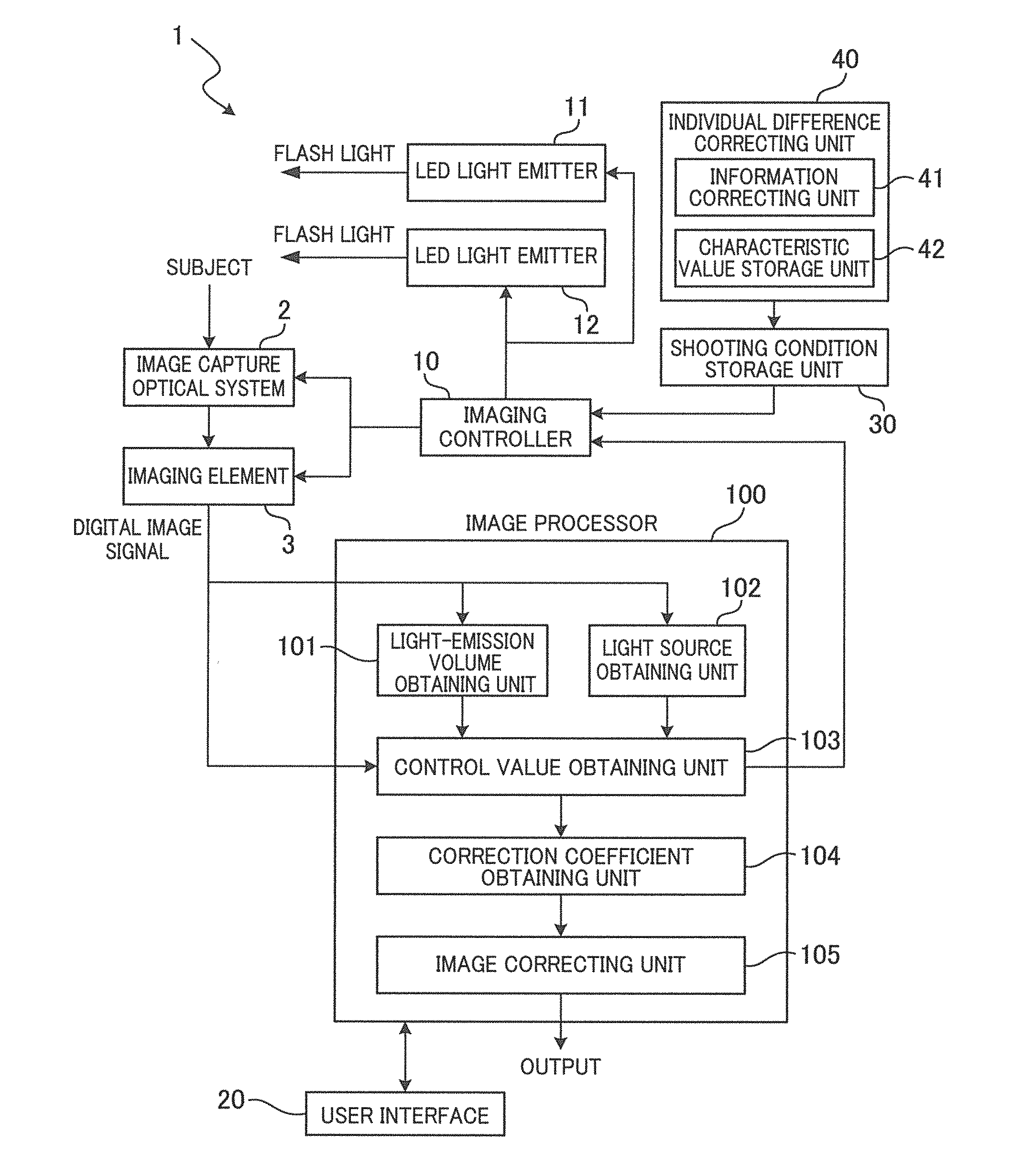
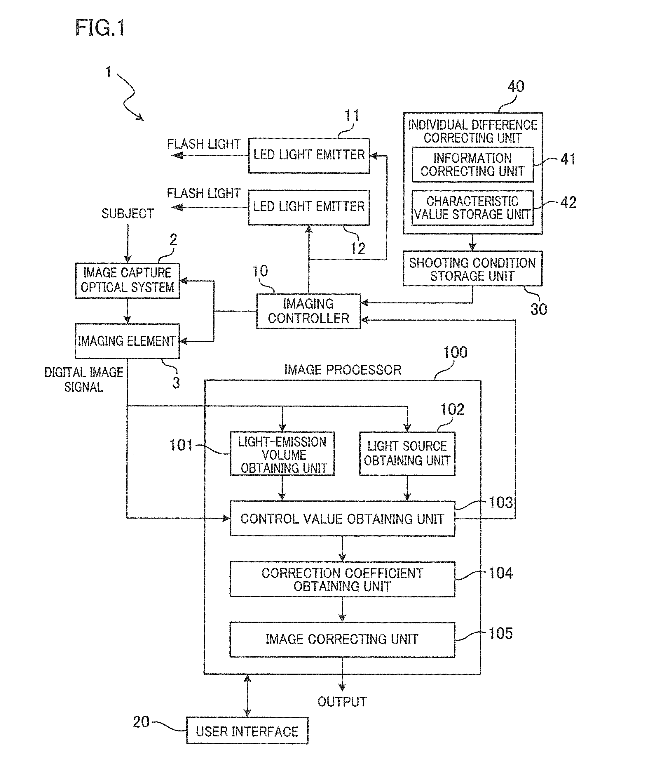
[0029]The following will describe an imaging device 1 related to an embodiment of the present invention, with reference to the drawings. As shown in FIG. 1, the imaging device 1 includes an image capture optical system 2, an imaging element 3, an imaging controller 10, LED light emitters 11 and 12, a user interface 20, a shooting condition storage unit 30, an individual difference correcting unit 40, and an image processor 100. The image capture optical system 2 includes a diaphragm and various types of lenses including a focus lens. The image capture optical system 2 is configured to introduce light from a subject to the imaging element 3 so that an image is formed on the imaging element 3. The imaging element 3 is a CMOS (complementary metal oxide semiconductor) image sensor. The imaging element 3 includes: color filters arranged in a predetermined pattern; a photoelectric conversion element configured to output an analog signal corresponding to the intensity of light received thr...


PUM


Abstract

A first line passing through a coordinate point which represents the light-source color of ambient light is drawn so as to cross a line segment connecting two coordinate points which points respectively represent colors of light emitted from the two light-emitting sources. An image of a subject is captured while light is emitted from the two light-emitting sources toward the subject in such a manner that the volumes of light emitted from the two light-emitting sources respectively correspond to those represented by a predetermined point which is, or close to, the intersection point of the first line and the line segment on the basis of the intersection point and light volume information. A White Balance adjustment correction value is obtained on the basis of light volume information with respect to the two light-emitting sources, the predetermined point, and the point representing the light-source color.

Description

BACKGROUND OF THE INVENTION[0001]The present invention relates to an image capturing method. In particular, the present invention relates to an image capturing method including White Balance adjustment on a captured image.[0002]The color of flash light (light from a flash) is usually different from the color of ambient light. Thus, when performing White Balance adjustment, the following question may arise: on the basis of which area in a captured image White Balance adjustment should be made. For example, between a subject closer to a device and a subject farther from the device, there is a difference in the ratio of flash light to ambient light applied to the subject. Because of this, depending on which of subject areas in the captured image is used for the White Balance adjustment, the result of the White Balance adjustment differs. Thus, the question is, on the basis of which subject area White Balance adjustment should be performed arises.[0003]One of possible ways to deal with ...

Claims


Application Information

Patent Timeline
Patent Type & Authority Applications(United States)
IPC IPC(8): H04N9/73H04N5/225H04N23/75
CPCH04N9/735H04N5/2354H04N5/2352H04N5/2256H04N23/84H04N23/88G03B15/05G03B33/00G03B7/17H04N23/76H04N23/74H04N23/56H04N23/72H04N23/80
Inventor SAKO, YASUSHIOKUNO, TSUTOMU
Owner RDA TECH
Why Eureka
Eureka Blog
Learn More