Switch control apparatus for electric plant

Active Publication Date: 2016-06-30
PIZZATO ELETTRICA
View PDF2 Cites 3 Cited by
  • Summary
  • Abstract
  • Description
  • Claims
  • Application Information

AI Technical Summary

Benefits of technology

The present invention aims to provide a switch control apparatus for electric plants that has high efficiency and low cost. The apparatus has several technical features such as stable position of contact units, easy installation and quick wiring, and accommodation of changes in contact units without compromising coupling stability. These features make the apparatus highly reliable and effective in controlling electric plants. The substantially box-shaped element also allows absorption of both axial and transverse stresses, which further enhances the stability of the apparatus.

Problems solved by technology

Nevertheless, prior art solutions do not ensure stable anchorage of the contact units with their respective actuators, particularly if control apparatus are subjected to shocks caused by accidental falls or impacts by users.
While a higher stability is imparted to each contact unit in this solution, only axially-directed forces may be counteracted, and no resistance is afforded to lateral stresses, whereby the risk of separation is not totally prevented.
Furthermore, as the cage is positioned, it may block the passages that are formed in the enclosure on the contact unit to allow access to the terminals of the fixed contacts and introduction of the terminals of the electric circuits, thereby adding complexity to the installation process.
A further serious drawback is that this particular type of anchor means is not adapted to pushbutton stations that allow coupling of various numbers of contact units to a single contact, which makes the entire apparatus poorly flexible.
Nevertheless, once again protection is restricted, as the plate does not ensure any lateral support.
Furthermore, like in the previous case, the plate covers the entire passages formed in the enclosure, and cannot accommodate any change in the number, configuration and type of contact units that can be received in the pushbutton station at the same time.

Method used


Image

  • Switch control apparatus for electric plant
  • Switch control apparatus for electric plant
  • Switch control apparatus for electric plant

Examples


Embodiment Construction

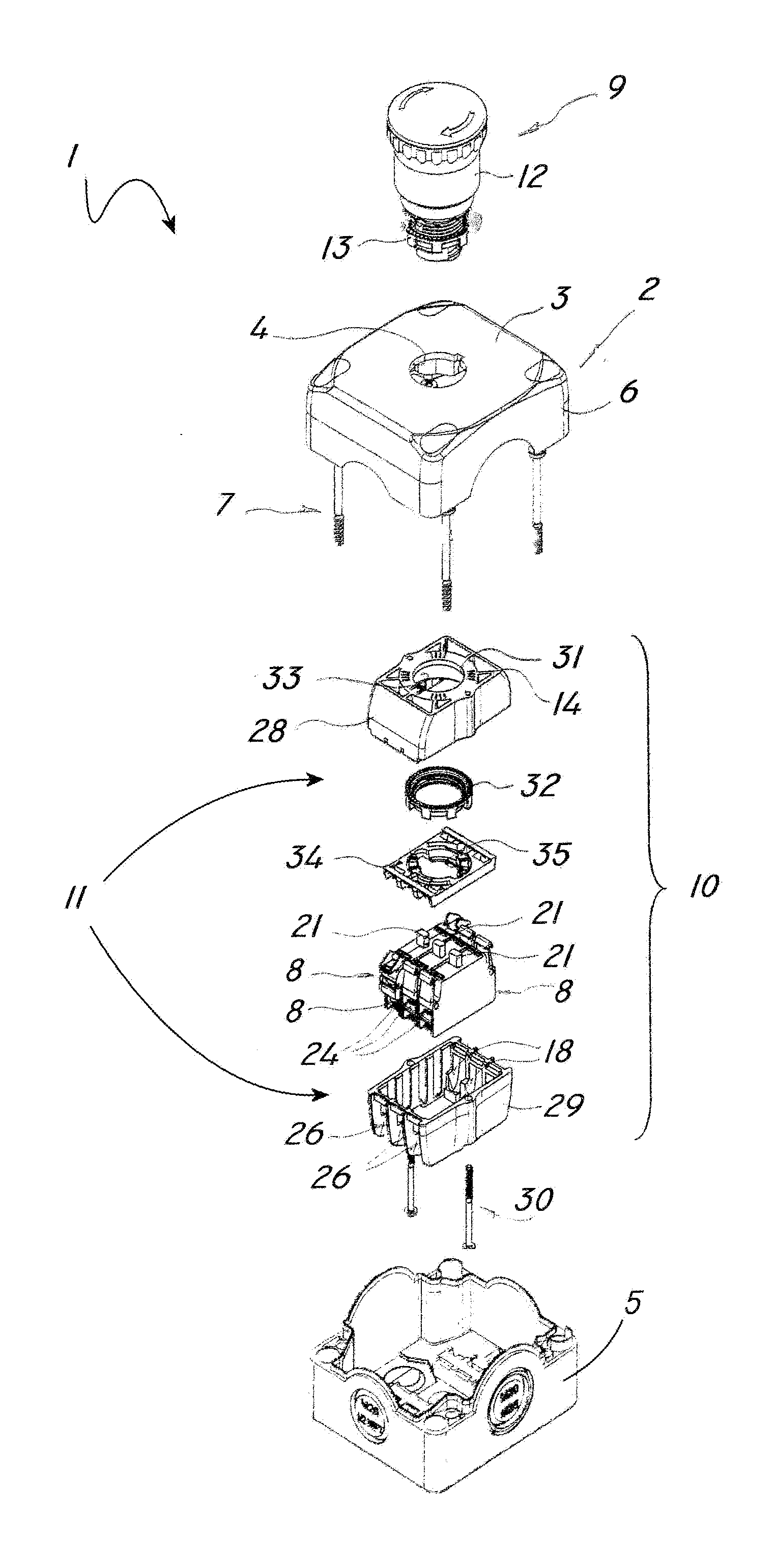
[0034]Referring to the above figures, a switch apparatus is shown, which is designed to control electric plants, namely plants for handling or transportation such as, without limitation, elevators, hoists, escalators, cranes, bridge cranes, and the like.

[0035]Particularly, FIG. 1 shows an apparatus of the control pushbutton station type, generally referenced 1, which has a box-like body 2 adapted for anchorage to a fixed or movable part of an electric plant, not shown and known per se, and having a closing panel 3 with a passage 4 formed therethrough.

[0036]In the illustrated embodiment, the box-like body 2 has a lower container portion 5, which may be anchored in a known manner to a fixed or movable support of the plant or to a suspension cable for the passage of electric cables, and an upper closing cover 6, which is adapted to be stably and removably coupled to the lower portion 5 by first screw means 7 or the like, to define a closed box-like body 2.

[0037]Here, the passage 4 is f...


PUM


Abstract

A switch control apparatus for electric plants includes, a box-like body which is adapted to be anchored to a fixed o movable part of an electric plant and has a closing panel with at least one passage therethrough, at least one contact unit which is accommodated in the box-like body at the passage and is adapted to be electrically connected to at least one respective electric circuit of the plant for selective open / close control thereof, at least one actuator which is adapted to interact with the contact unit for the latter to ensure selective opening / closing of the respective circuits, an anchor system for anchoring the contact unit to the actuator. The anchor system includes a container member which is adapted to enclose and contain the contact unit and to be anchored to the closing panel in the box-like body for stably securing the contact unit on the actuator.

Description

FIELD OF THE INVENTION[0001]The present invention generally finds application in the field of electric control devices and particularly relates to a switch control unit for electric plants.BACKGROUND ART[0002]Electric switch control apparatus, such as switchboard boxes or control pushbutton stations of electric plants for handling or transportation, generally include a box-like body, which houses one or more electric switch devices designed to be connected to the electric terminals of respective electric circuits.[0003]Particularly, switch devices include one or more switch contact units, of single- or double-contact type, each having an enclosure that contains pairs of fixed and movable contacts associated with an actuating cursor.[0004]The latter is designed to interact with an actuator, such as a pushbutton or a selector, which is anchored to the box-like body, generally to a movable or removable part thereof.[0005]For example, in the case of switchboards, actuators are anchored ...

Claims


Application Information

Patent Timeline
IPC IPC(8): H01H13/04H01H1/58H01H3/02
CPCH01H13/04H01H2223/058H01H1/58H01H3/02H01H3/022H01H3/60H01H13/503
Inventor PIZZATO, MARCO
Owner PIZZATO ELETTRICA
Why Eureka
Try Eureka