
Adapter device for retrofitting in lighting arrangements

a technology of adapter device and lighting arrangement, which is applied in the direction of lighting support device, coupling device connection, lighting and heating apparatus, etc., can solve the problems of slow and complicated operation, and device does not provide a satisfactory fastening of led lamps in lamp fixtures, etc., to facilitate the logistics of luminaires and/or lighting modules, easy, convenient and intuitive operation, and save time and tooling costs

Inactive Publication Date: 2016-06-23
SIGNIFY HLDG BV
View PDF11 Cites 7 Cited by
  • Summary
  • Abstract
  • Description
  • Claims
  • Application Information

AI Technical Summary

Benefits of technology

The present invention provides an adapter device for attaching a lighting module to a luminaire without the need for adjusting the luminaire. The adapter device includes a force clamping mechanism that allows for easy and convenient attachment of the lighting module without the need for adjusting the luminaire. The adapter device is easy to operate, convenient, and saves time and money for the customer and the installer. It also facilitates the logistics of the luminaire and lighting module. The adapter device is advantageous in cases where the lighting module needs to be retrofitted in an indoor or outdoor setting, as it allows for easy and convenient replacement of the lighting module. The adapter device is also advantageous in that it has a low number of components, making it inexpensive and easy to recycle.

Problems solved by technology

However, the mounting of the LED lamp is still complicated, awkward and circumstantial.
Furthermore, the shown device does not provide a satisfactory fastening of the LED lamp in the lamp fixture.
As a consequence, the fitting of the LED lamp in the lamp fixture according to the prior art leads to a slow and complicated operation.

Method used


Image

  • Adapter device for retrofitting in lighting arrangements
  • Adapter device for retrofitting in lighting arrangements
  • Adapter device for retrofitting in lighting arrangements

Examples


Embodiment Construction

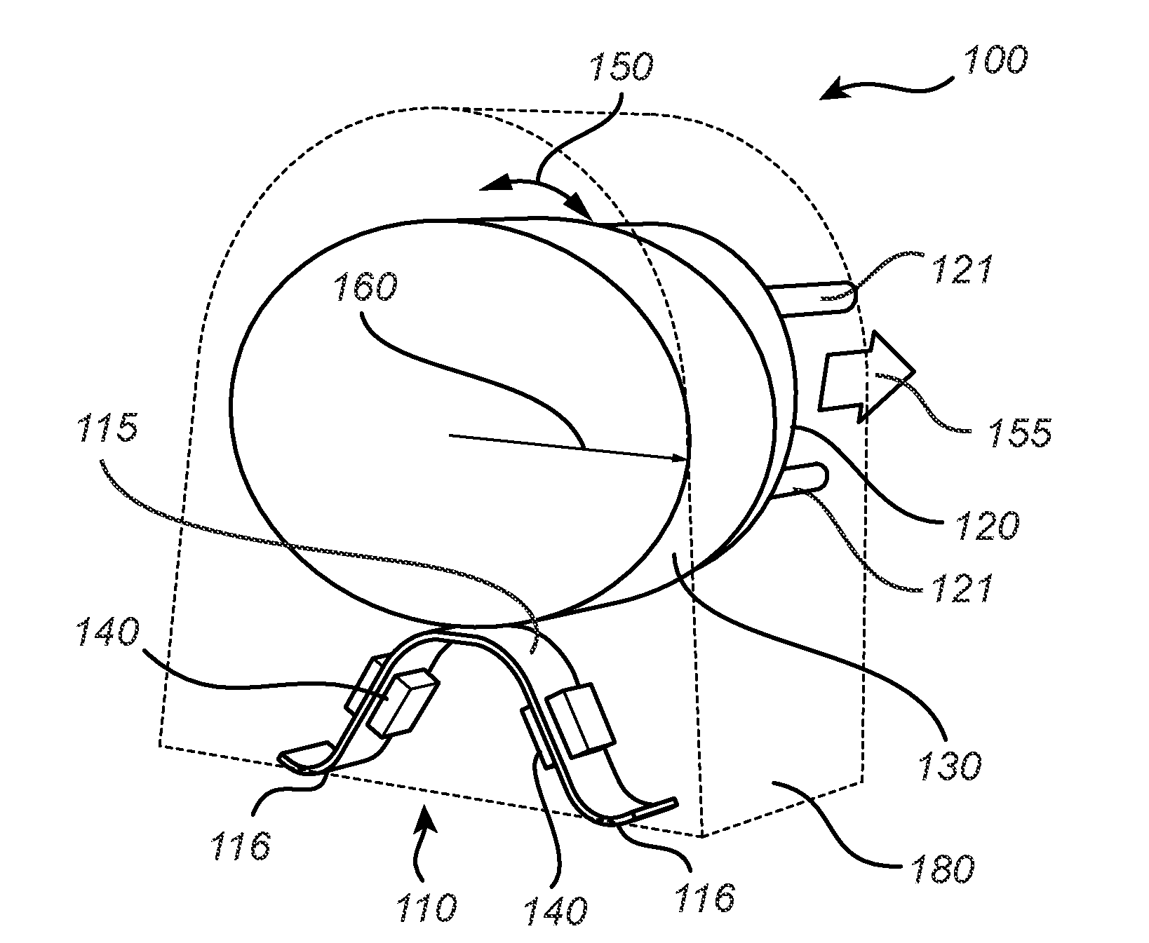
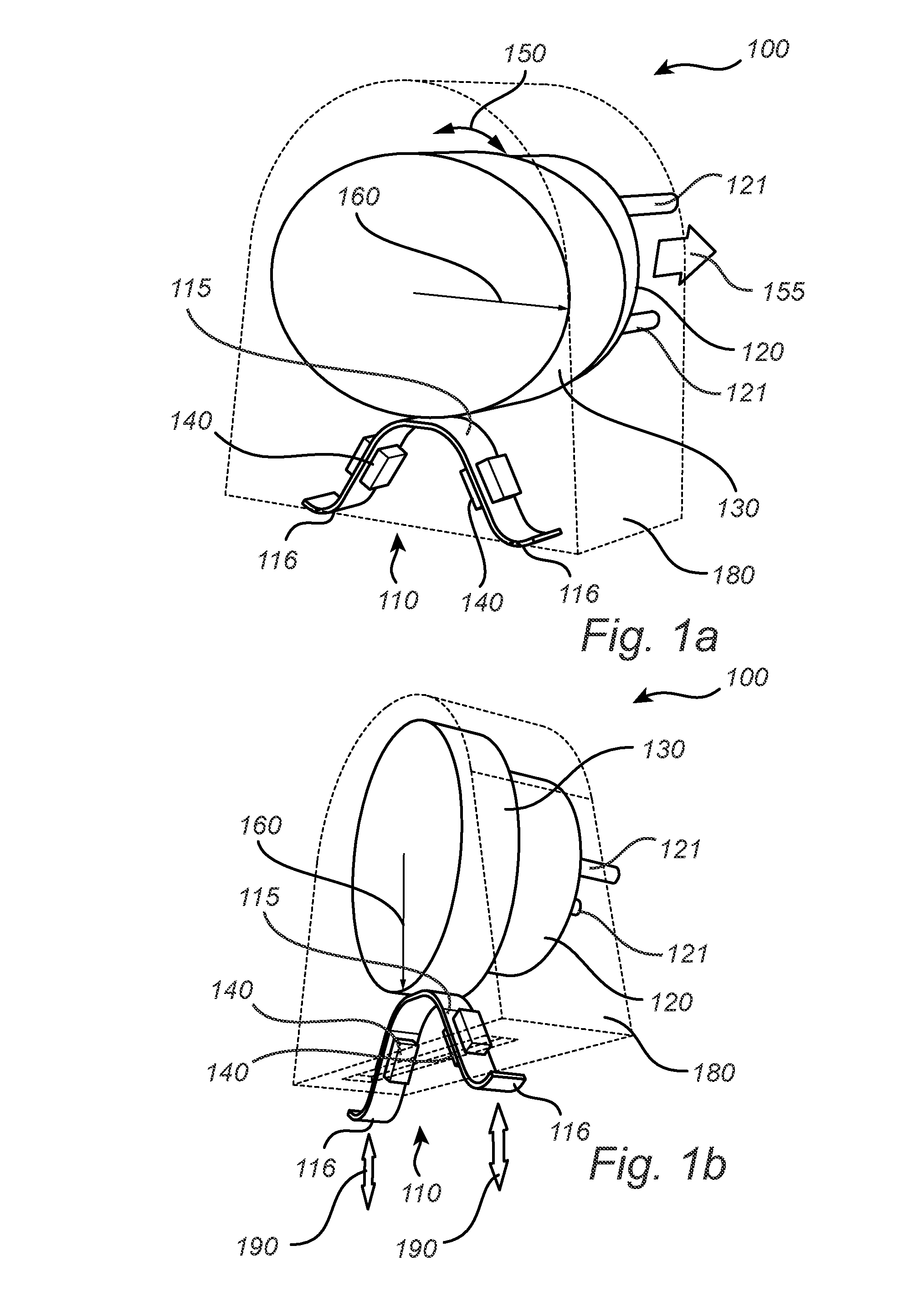
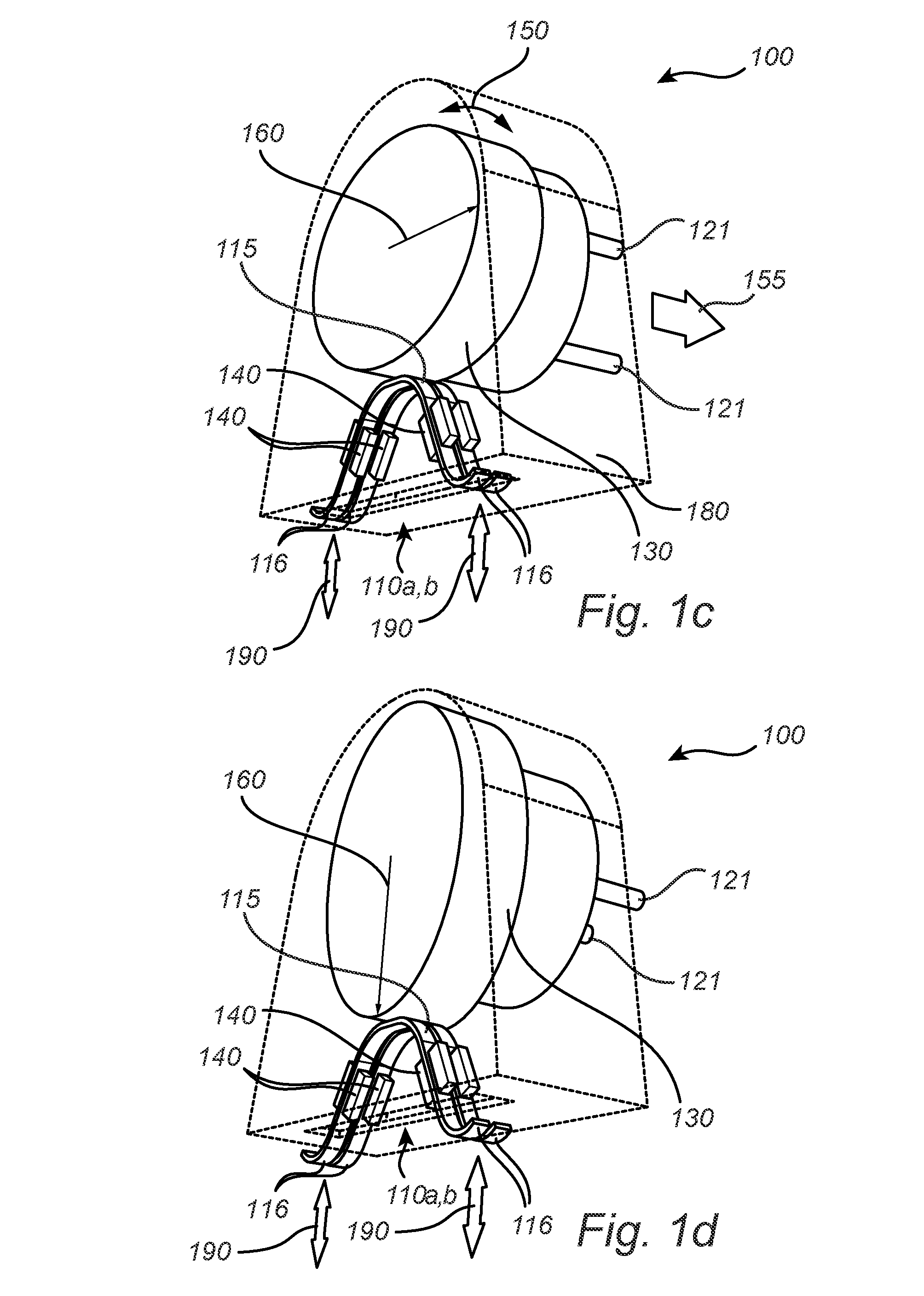
[0036]FIG. 1a is a schematic view of an adapter device 100 according to an exemplifying embodiment of the present invention. The adapter device 100 comprises a resilient element 110. The resilient element 110 in FIG. 1a is exemplified as a leaf spring 110, comprising an arched portion 115 and two end portions 116. It will be appreciated that the resilient element 110 may be substantially any resilient or elastic element such as a spring, coil, (spring) clip, elastomeric material, or the like. The resilient element 110 may be fastened to the adapter device 100 by fastening elements 140, here exemplified by a pair of clips 140. Alternatively, the resilient element 110 may be connected or fastened to the adapter device 100 by other devices and / or arrangements. Furthermore, the resilient element 110 may be fastened to the adapter device 100 such that movement and / or play of the resilient element 110 is allowed, e.g. by a flexible connection of the resilient element 110 to the adapter de...


PUM


Abstract

An adapter device (100) for releasable attachment of a lighting module in a luminaire. The adapter device comprises at least one resilient element (110, 110a, 110b) arranged to abut the lighting module. The adapter device further comprises an electrical interface (120), arranged for electrical connection to the luminaire, wherein the electrical interface is mechanically engageable with the at least one resilient element. At least a portion (130) of the electrical interface is rotatably arranged in the adapter device and comprises an arm portion (160) which elongates in a rotational plane of the at least one portion of the electrical interface. The arm portion is arranged to bias the at least one resilient element dependently on the rotation of the at least one portion of the electrical interface, such that the at least one resilient element, in a biased state, is arranged to clamp the lighting module to the luminaire.

Description

FIELD OF THE INVENTION[0001]The present invention generally relates to an adapter device. More specifically, the adapter device relates to retrofitting in lighting arrangements.BACKGROUND OF THE INVENTION[0002]The use of light-emitting diodes (LED) for illumination purposes continues to attract attention. Compared to incandescent lamps, fluorescent lamps, neon tube lamps, etc., LEDs provide numerous advantages such as a longer operational life, a reduced power consumption, and an increased efficiency related to the ratio between light energy and heat energy.[0003]Due to the advantageous aspects of the use of LEDs, the interest has rapidly increased to replace conventional light sources with LEDs in many lighting arrangements, also called retrofitting. It will be appreciated that LEDs may replace conventional light sources in virtually any kind of lighting, e.g. commercial or domestic lighting arrangements, advertising signs, traffic signals, exit signs, etc. The light source replace...

Claims


Application Information

Patent Timeline
Patent Type & Authority Applications(United States)
IPC IPC(8): F21V19/00F21K99/00H01R33/08F21V23/06
CPCF21V19/0085F21V23/06F21Y2103/003F21V19/001H01R33/08F21K9/17F21V19/00F21V19/003F21V19/0035F21V19/004F21V19/0075H01R31/06H01R33/0863F21Y2103/10F21Y2115/10F21K9/272
Inventor KESER, MERIJNDE JONG, ERIK ADRIANUS ANDREAS
Owner SIGNIFY HLDG BV
Learn More