
Multi-Purpose Tool and Tool Attachments

a multi-purpose tool and tool attachment technology, applied in the direction of manufacturing tools, hoisting equipment, hand cultivators, etc., can solve the problems of limited function of reference and many other known configurations of multi-purpose tools and tool attachments, and the inability of combination tools to allow both a left-hand and a right-hand orientation of tool attachments, etc., to achieve quick and easy attachment and comfortable grip

Inactive Publication Date: 2016-06-23
SERE IND
View PDF19 Cites 5 Cited by
  • Summary
  • Abstract
  • Description
  • Claims
  • Application Information

AI Technical Summary

Benefits of technology

The invention provides a multi-purpose tool with a utility bar and universal connectors for quick and easy attachment of different tool attachments. The bar is made of an elongated structural member covered by an overmold, which helps to absorb shock / impact forces and is more comfortable to grip. The elongated member has recesses to improve its strength-to-weight ratio. The handle attachment has a t-shaped member with a handle portion and a stem portion with blunt and pointed ends, as well as one or more through holes for attachment points. The stem portion has a universal connector for easy coupling with the utility bar. Overall, the invention provides a tool that is comfortable, easy to use, and can be configured for different tasks.

Problems solved by technology

Unfortunately, the threaded connectors of the combination tool do not allow for both a left-hand and a right-hand orientation of tool attachments because the threaded connectors are unidirectional.
Moreover, the threaded connectors take time to attach and detach different tool attachments and do not always orient the tool attachments in a consistent manner (e.g., the T-union handle attachment may not always be oriented in plane with the spade attachment if either attachment is over rotated or if the threads are worn).
Unfortunately, these configurations and designs also suffer from one or more of the drawbacks discussed above.
In addition, these references and many other known configurations for multi-purpose tools and tool attachments have very limited function.
In addition, the bar itself typically does not server any function other than as a handle or connector for attaching different tool attachments.

Method used


Image

  • Multi-Purpose Tool and Tool Attachments
  • Multi-Purpose Tool and Tool Attachments
  • Multi-Purpose Tool and Tool Attachments

Examples


Embodiment Construction

[0111]The following description includes information that may be useful in understanding the present invention. It is not an admission that any of the information provided herein is prior art or relevant to the presently claimed invention, or that any publication specifically or implicitly referenced is prior art.

[0112]The following discussion provides many example embodiments of the inventive subject matter. Although each embodiment represents a single combination of inventive elements, the inventive subject matter is considered to include all possible combinations of the disclosed elements. Thus if one embodiment comprises elements A, B, and C, and a second embodiment comprises elements B and D, then the inventive subject matter is also considered to include other remaining combinations of A, B, C, or D, even if not explicitly disclosed.

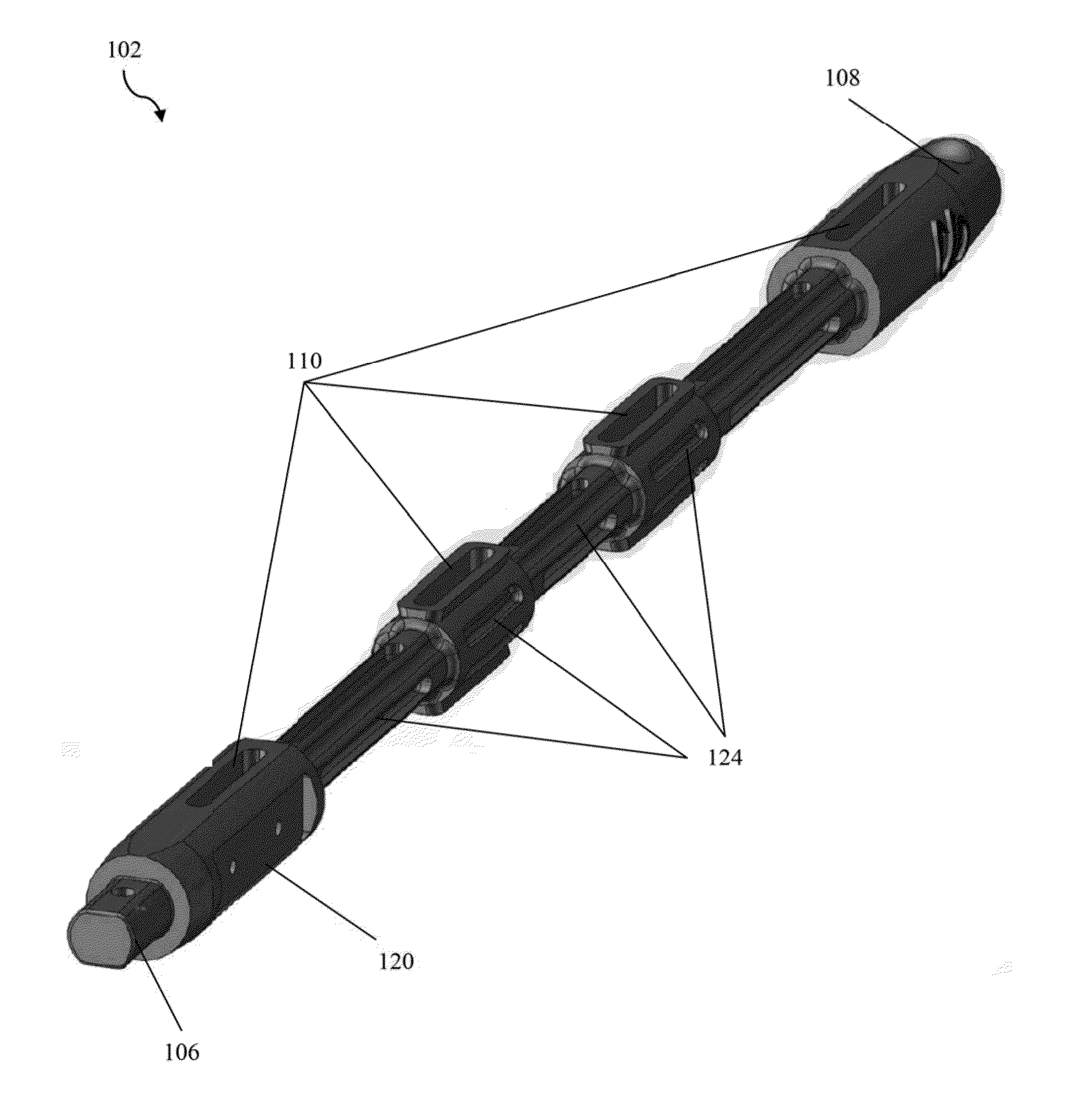
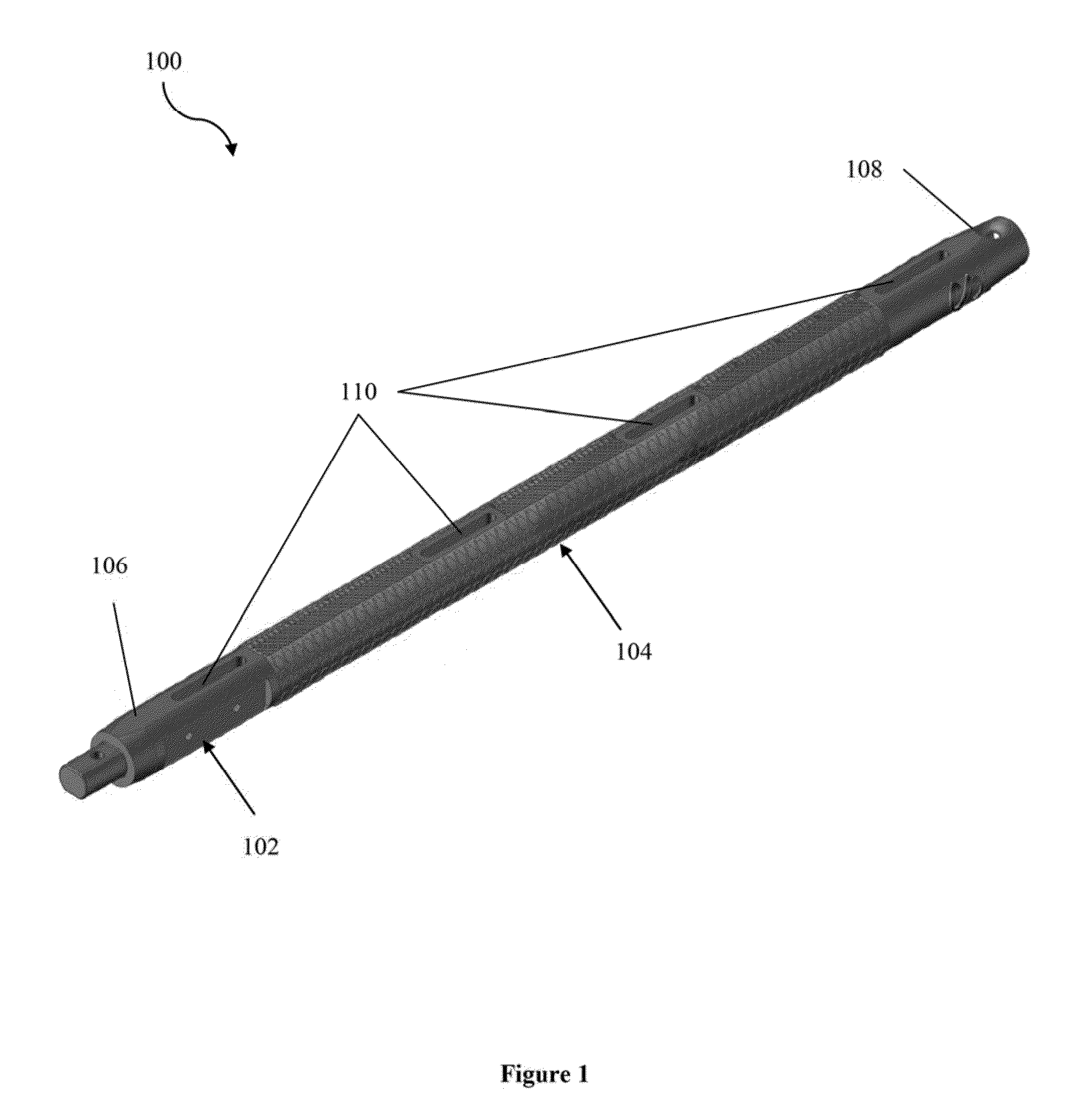
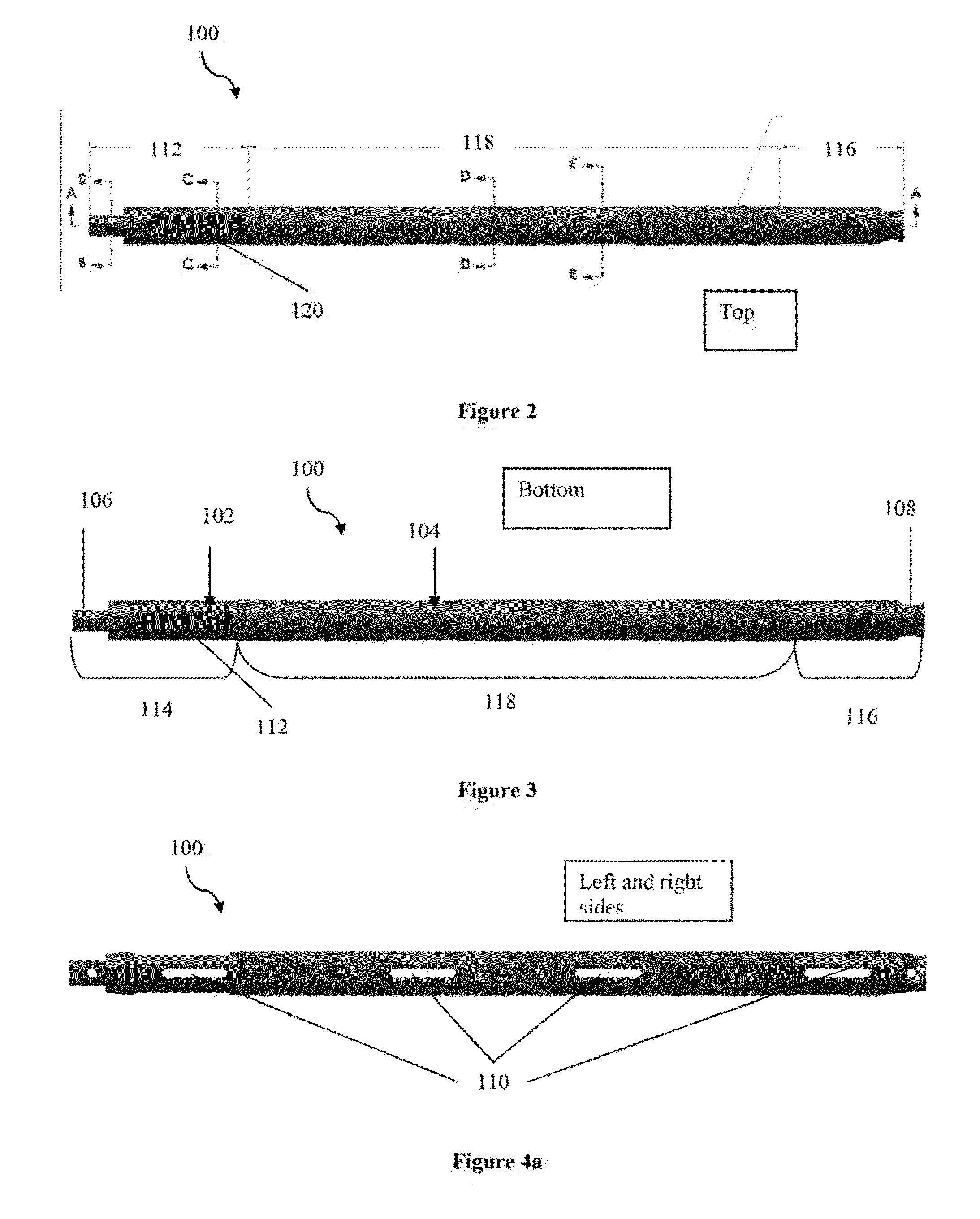
[0113]FIG. 1 is a perspective view of a multi-purpose utility bar 100. Bar 100 has an elongated structural member 102 and an overmold 104 covering...


PUM


Abstract

A multi-purpose tool and tool attachments have been described. The multi-purpose tool comprises a utility bar that has an elongated structural member partly covered by an overmold, and universal connectors on its two ends. The cross section of the elongated member is crossed-shaped and has a plurality of recesses, which helps to optimize the weight-to-strength ratio of the bar. The universal connectors are male and female snap-fit engagements that allow for different tool attachments to be quickly and easily attached to the ends of the bar in both a right-hand and left-hand orientation. The connectors also allow several utility bars to be connected in series to make a longer utility bar. The tool attachments comprise a handle-hammer-pick attachment, a shovel head counterweight, a spear head, an extractor attachment, a breaching tool attachment, and a monopod sniper attachment. Each tool attachment is designed to have multiple functions.

Description

FIELD OF THE INVENTION[0001]The field of the invention is multi-purpose tools and tool attachments.BACKGROUND[0002]The background description includes information that may be useful in understanding the present invention. It is not an admission that any of the information provided herein is prior art or relevant to the presently claimed invention, or that any publication specifically or implicitly referenced is prior art.[0003]Various configurations of multi-purpose tools are known. U.S. Pat. No. 576,756, for example, discloses a “combination tool,” that has a bar with threaded ends and various tool attachments (e.g., spade, hammer, pick, hatchet, etc.) that can be threadably coupled to the ends of the bar. The interchangeable tool attachments advantageously provide multiple functions for the combination tool, thus reducing weight and space. Unfortunately, the threaded connectors of the combination tool do not allow for both a left-hand and a right-hand orientation of tool attachmen...

Claims


Application Information

Patent Timeline
Patent Type & Authority Applications(United States)
IPC IPC(8): B25F1/02B25D7/00A42B3/04B25J1/04A01B1/08B25D1/04B25F1/00
CPCB25F1/02B25D1/04B25D7/00A42B3/0406B25J1/04A01B1/08B25F1/006
Inventor LANGAN, TIMOTHY M.
Owner SERE IND
Learn More