Decoupling Visibility Bins and Render Tile Dimensions for Tiled Rendering

a technology of visibility bins and tile dimensions, applied in the field of computer processors, can solve the problems of mapping could encounter problems, and non-graceful degradation of performan

Active Publication Date: 2016-06-16
INTEL CORP
View PDF2 Cites 5 Cited by
  • Summary
  • Abstract
  • Description
  • Claims
  • Application Information

AI Technical Summary

Problems solved by technology

This 1:1 mapping could encounter problems when the number of render tiles exceeds the number of visibility bins that the Graphical Processing Unit (GPU) could generate in parallel.
This is because multiple visibility passes are needed and it causes non-graceful degradation in performance.
This causes the non-graceful degradation in performance.

Method used


Image

  • Decoupling Visibility Bins and Render Tile Dimensions for Tiled Rendering
  • Decoupling Visibility Bins and Render Tile Dimensions for Tiled Rendering
  • Decoupling Visibility Bins and Render Tile Dimensions for Tiled Rendering

Examples


Embodiment Construction

[0024]In the following description, for the purposes of explanation, numerous specific details are set forth in order to provide a thorough understanding of the embodiments of the invention described below. It will be apparent, however, to one skilled in the art that the embodiments of the invention may be practiced without some of these specific details. In other instances, well-known structures and devices are shown in block diagram form to avoid obscuring the underlying principles of the embodiments of the invention.

[0025]Exemplary Graphics Processor Architectures and Data Types

Overview—FIGS. 1-3

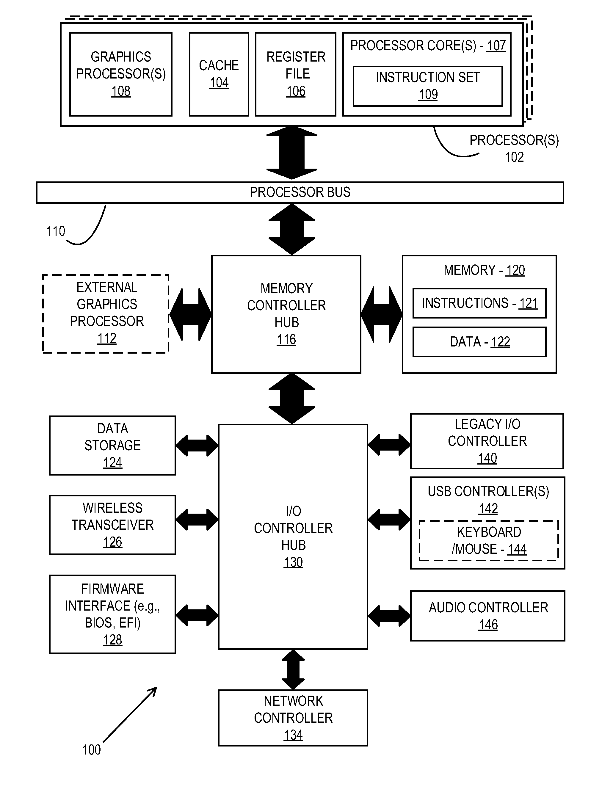
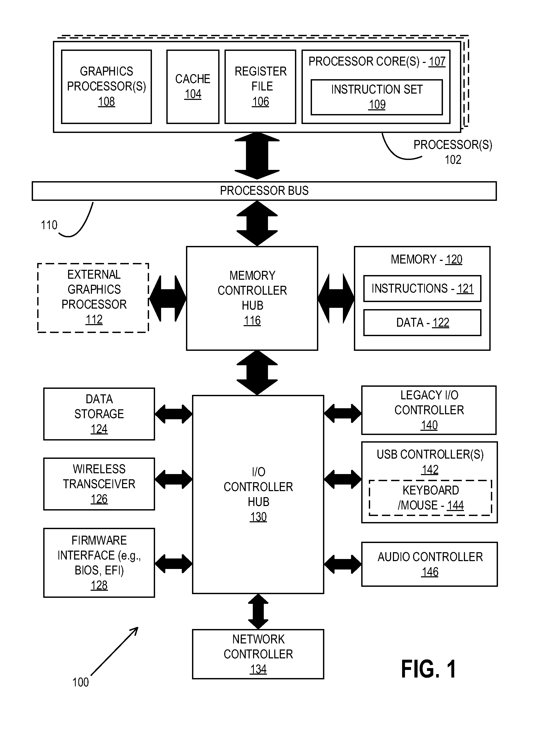
[0026]FIG. 1 is a block diagram of a data processing system 100, according to an embodiment. The data processing system 100 includes one or more processors 102 and one or more graphics processors 108, and may be a single processor desktop system, a multiprocessor workstation system, or a server system having a large number of processors 102 or processor cores 107. In on embodiment, the da...


PUM


Abstract

An apparatus and method are described for decoupling visibility bins and render tile dimensions for tiled rendering. In one embodiment of the invention, a single visibility pass over the scene objects is performed and all the visibility bins are generated in parallel. This allows for high performance when the number of render tiles exceeds the number of visibility bins. The regions upon which visibility testing/recording is done is decoupled from the render tile regions in one embodiment of the invention. This allows a given visibility bin to map to multiple render tiles, thus allowing a fixed number of visibility bins to support any number of render tiles.

Description

FIELD OF THE INVENTION[0001]This invention relates generally to the field of computer processors. More particularly, the invention relates to an apparatus and method for decoupling visibility bins and render tile dimensions.BACKGROUND DESCRIPTION[0002]In some tile rendering architectures, there is a 1:1 mapping between the visibility bins or regions and the render tiles. This 1:1 mapping could encounter problems when the number of render tiles exceeds the number of visibility bins that the Graphical Processing Unit (GPU) could generate in parallel. This is because multiple visibility passes are needed and it causes non-graceful degradation in performance.[0003]For example, FIG. 11 illustrates a prior-art visibility bin scheme. The visibility bins 1106 and 1108 are mapped 1:1 to the render tiles 1114 and 1116 respectively after performing the tile render pass stages 1110 and 1112. When the number of render tiles exceeds the number of visibility bins under the prior-art visibility bin...

Claims


Application Information

Patent Timeline
Patent Type & Authority Applications(United States)
IPC IPC(8): G06T15/40G06T1/20
CPCG06T1/20G06T15/40G06T15/005
Inventor DOYLE, PETER L.
Owner INTEL CORP
Why Eureka
Try Eureka