Double-stator rotating electric machine

a rotating electric machine and double-stator technology, applied in the direction of magnetic circuit rotating parts, magnetic circuit shape/form/construction, windings, etc., can solve the problem of difficult to minimize the coil end height, and achieve the effect of improving the performance reducing the coil end height, and reducing the size of the rotating electric machin

Active Publication Date: 2016-06-09
DENSO CORP
View PDF6 Cites 8 Cited by
  • Summary
  • Abstract
  • Description
  • Claims
  • Application Information

AI Technical Summary

Benefits of technology

[0013]With the above configuration, the magnetomotive forces of the outer and inner stators are offset in phase from each other by the offset angle θ that is greater than 0° and less than 180° in electrical angle. That is, the magnetomotive forces of the outer and inner stators are arranged neither in parallel nor in series with each other. Consequently, compared to the case of arranging the magnetomotive forces of the outer and inner stators parallel to each other (i.e., θ=0° in electrical angle), it is more difficult for magnetic saturation of the rotor to occur and thus it is possible to improve the performance of the rotating electric machine. Moreover, compared

Problems solved by technology

However, in this case, it may be diff

Method used


Image

  • Double-stator rotating electric machine
  • Double-stator rotating electric machine
  • Double-stator rotating electric machine

Examples


Embodiment Construction

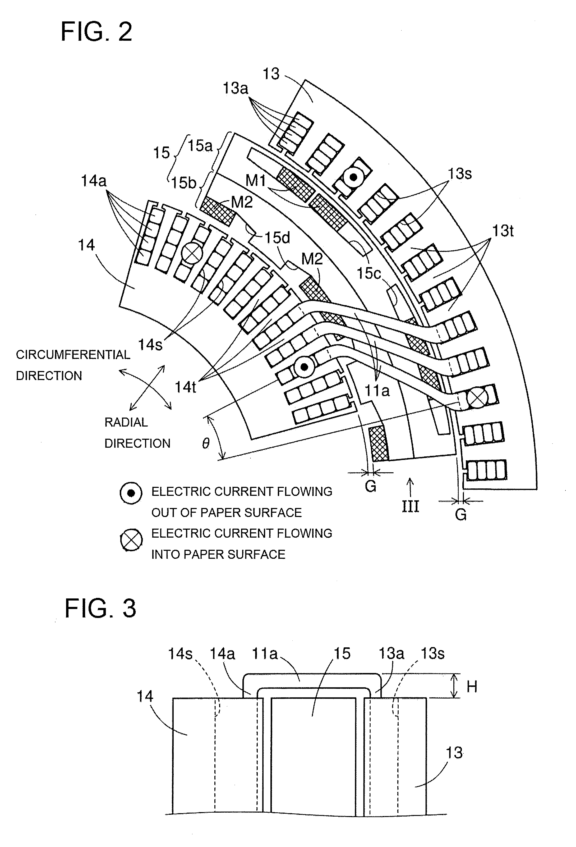
[0036]FIG. 1 shows the overall configuration of a double-stator rotating electric machine 10 according to an exemplary embodiment.

[0037]In this embodiment, the rotating electric machine 10 is configured as a motor-generator that selectively functions either as an electric motor or as an electric generator.

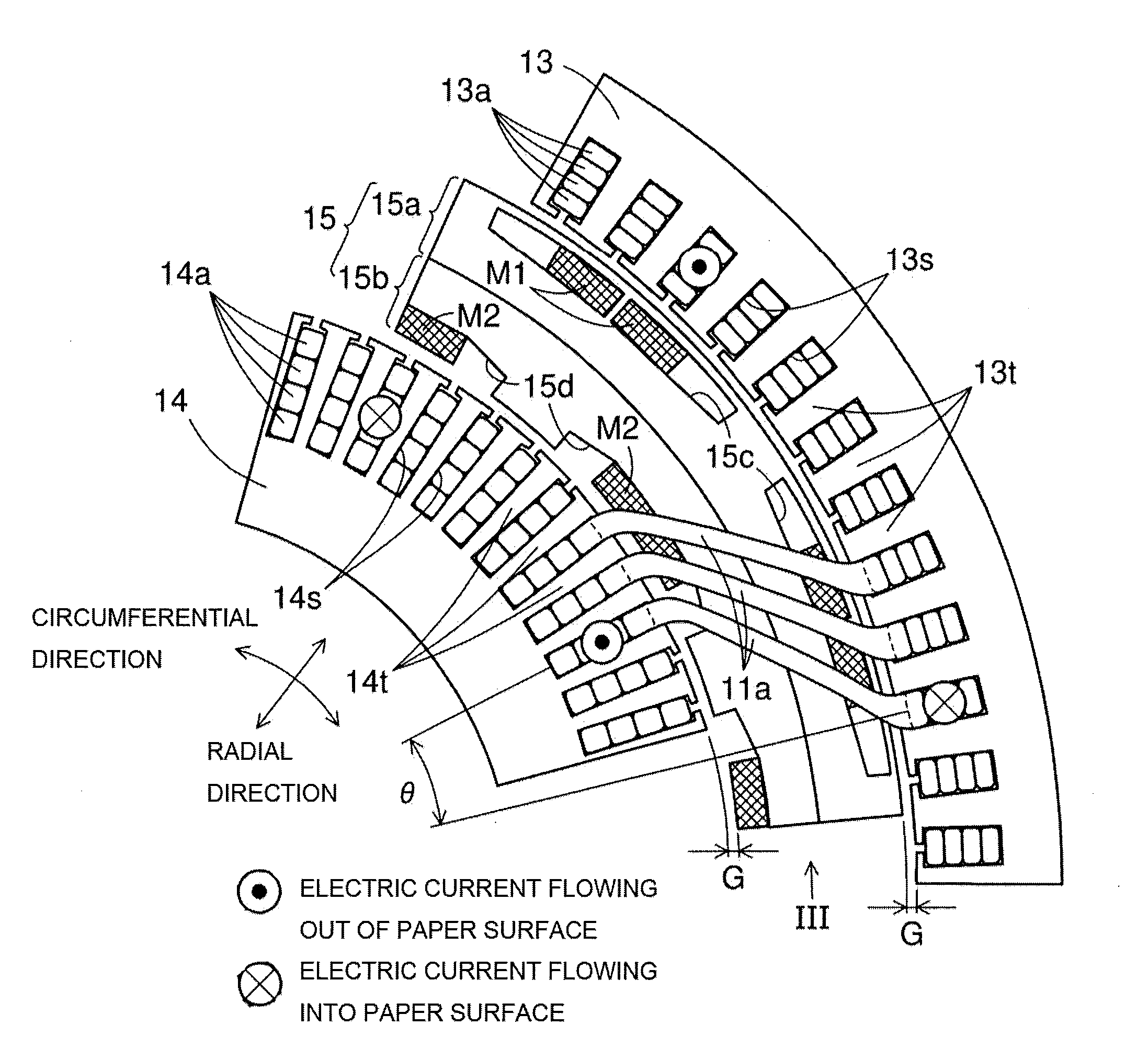
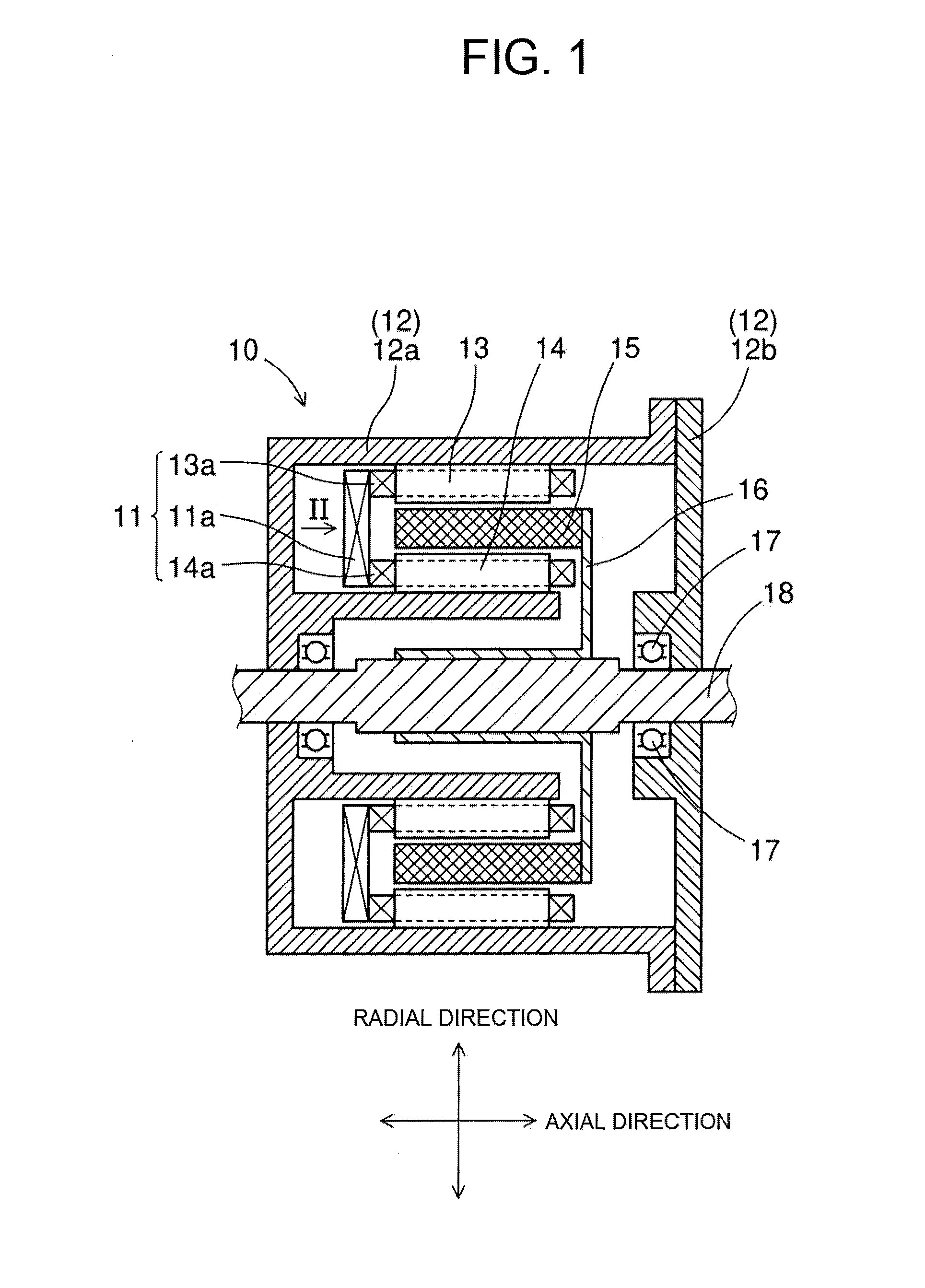
[0038]As shown in FIG. 1, the rotating electric machine 10 includes a housing 12, an outer stator 13, an inner stator 14, a rotor 15, a disc 16, a pair of bearings 17 and a rotating shaft 18.

[0039]The housing 12 includes a main body 12a and a cover 12b. The main body 12a is substantially cup-shaped to have an open end. The cover 12b is disc-shaped and fixed to the main body 12a so as to cover the open end of the main body 12a.

[0040]Moreover, in the housing 12, there are provided the pair of bearings 17 via which the rotating shaft 18 is rotatably supported by the housing 12. In addition, the rotating shaft 18 may have any shape suitable for rotation.

[0041]The outer stator 13 is fi...


PUM


Abstract

A double-stator rotating electric machine includes a rotor, an outer stator having an outer multi-phase coil wound thereon, and an inner stator having an inner multi-phase coil wound thereon. Each corresponding pair of phase windings of the outer and inner multi-phase coils are formed of at least one common electric conductor wire. The electric conductor wire includes a bridging portion that bridges the corresponding pair of phase windings of the outer and inner multi-phase coils across the rotor. The bridging portion extends obliquely with respect to both radial and circumferential directions of the rotor so that radially outer and radially inner ends of the bridging portion, which are respectively connected to the corresponding pair of phase windings of the outer and inner multi-phase coils, are circumferentially offset from each other by an offset angle θ. The offset angle θ is greater than 0° and less than 180° in electrical angle.

Description

CROSS-REFERENCE TO RELATED APPLICATION[0001]This application is based on and claims priority from Japanese Patent Application No. 2014-247850 filed on Dec. 8, 2014, the content of which is hereby incorporated by reference in its entirety into this application.BACKGROUND[0002]1. Technical Field[0003]The present invention relates to double-stator rotating electric machines which include a rotor, an outer stator disposed radially outside the rotor, and an inner stator disposed radially inside the rotor.[0004]2. Description of Related Art[0005]Japanese Patent Application Publication No. JP2007261342A discloses an in-wheel motor which includes a rotor and a pair of outer and inner stators. The rotor is connected to a wheel shaft so as to rotate together with the wheel shaft. The outer stator is fixed to a housing so as to be positioned radially outside the rotor with an outer gap formed therebetween. The inner stator is fixed to the housing so as to be positioned radially inside the roto...

Claims


Application Information

Patent Timeline
IPC IPC(8): H02K16/04H02K1/27H02K3/28
CPCH02K16/04H02K1/27H02K3/28H02K1/276H02K1/2791
Inventor KUSASE, SHIN
Owner DENSO CORP
Why Eureka
Try Eureka