Reciprocating Pump Drive Assembly

a technology of reciprocating pump and drive assembly, which is applied in the direction of fluid removal, drilling accessories, borehole/well accessories, etc., can solve the problems of difficult or potentially unsafe access for maintenance, premature wear, etc., and achieves easy and safer access to the polish rod connection, reduces any off-axis stresses of the piston, and minimizes the potential for premature wear

Active Publication Date: 2016-06-09
AMIK OILFIELD EQUIP & RENTALS
View PDF3 Cites 2 Cited by
  • Summary
  • Abstract
  • Description
  • Claims
  • Application Information

AI Technical Summary

Benefits of technology

[0010]By providing a mounting frame which depends downwardly from the connection to the hydraulic actuators, the resulting mounting bracket connection to the polish rod can be recessed in elevation relative to the top end of the actuators. This results in an easier and safer access to the polish rod connection for maintenance. More importantly, the lower elevation on the polish rod connection provides a more stable support of the polish rod such that any off-axis load from the polish rod is accordingly at a lower elevation relative to the hydraulic actuators which in turn reduces any off-axis stresses of the piston relative to the cylinder of the hydraulic actuator. The reduced stresses minimize the potential for premature wear of the actuators.

Problems solved by technology

When used for reciprocating a polish rod, the weight of the polish rod string can place considerable off-axis stresses on the actuators which might result in premature wear, or failure in some instances.
Furthermore, due to the long stroke length of polish rod configurations, the connection of the polish rod to the actuators is necessarily at a high location above the wellhead which can be difficult or potentially unsafe to access for maintenance and the like.

Method used


Image

  • Reciprocating Pump Drive Assembly
  • Reciprocating Pump Drive Assembly
  • Reciprocating Pump Drive Assembly

Examples


Embodiment Construction

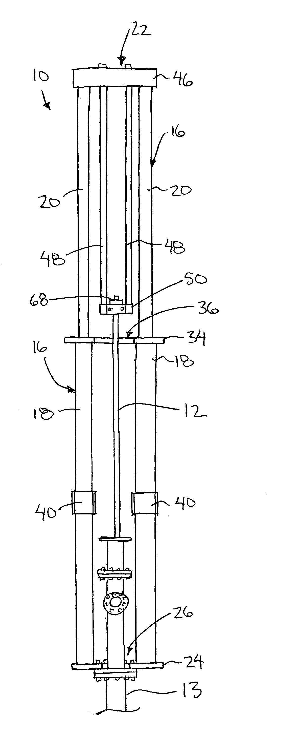
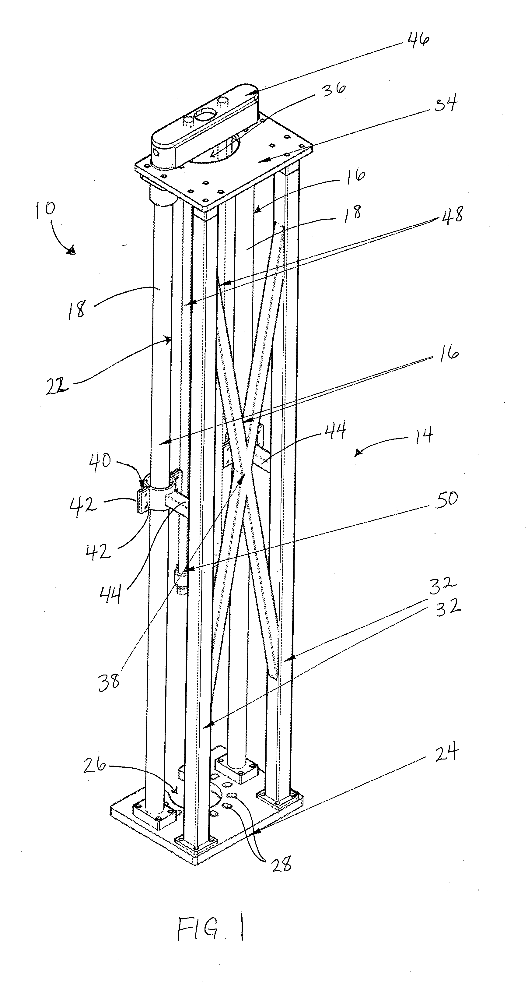
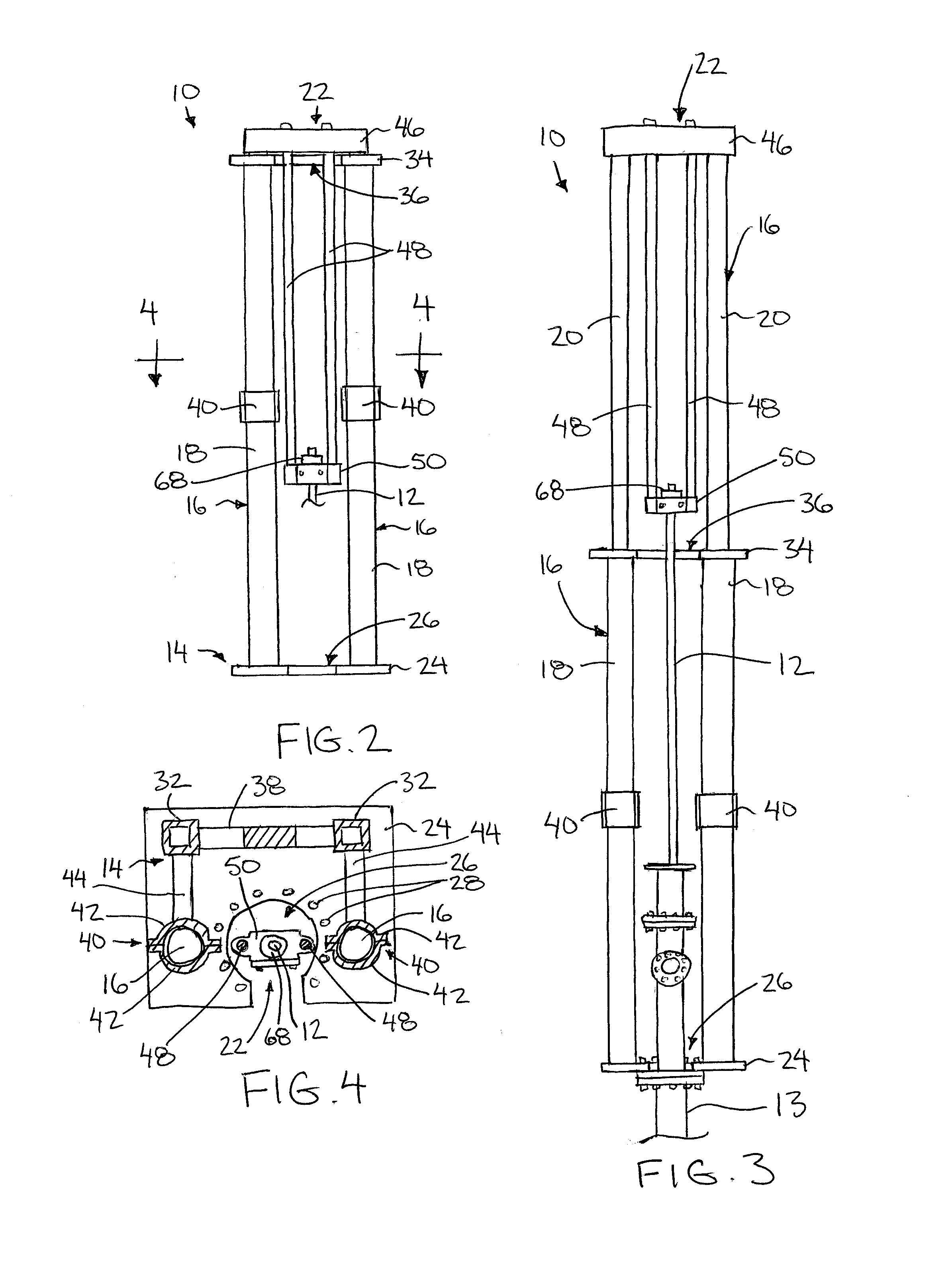
[0030]Referring to the accompanying figures, there is illustrated a reciprocating pump drive assembly generally indicated by reference numeral 10. The assembly 10 is particularly suited for use with a reciprocating pump of the type including a polish rod 12 arranged to be reciprocating relative to a pump casing locating various check valves therein for cooperation with the reciprocating polish rod to pump a fluid up through the well casing connected in series with the pump casing.

[0031]The assembly 10 generally includes a support frame 14 arranged to be mounted in fixed relation to the well casing. The assembly 10 further includes two hydraulic actuators 16 in which each actuator includes a cylinder portion 18, which is mounted in fixed relation on the support frame, and a piston portion 20 arranged to be reciprocated relative to the cylinder portion on the support frame. The assembly 10 yet further comprises a mounting frame 22 which is supported on the piston portions 20 of the hy...


PUM


Abstract

A reciprocating pump drive assembly for driving a reciprocation of a polish rod relative to a well casing includes a support frame which supports a pair of hydraulic actuators such that the cylinder portions thereof are fixed relative to the well casing. A mounting frame is supported at a top end thereof on the top ends of the piston portions of the hydraulic actuators so as to extend downwardly to a polish rod mounting bracket at the bottom end of the mounting frame. The top end of the polish rod is thus supported by the mounting frame so as to be suspended below the top end of the hydraulic actuators for improved access during servicing and for greater overall lateral stability of the drive assembly.

Description

FIELD OF THE INVENTION[0001]The present invention relates to reciprocating pump drive assembly for driving a reciprocating pump of the type including a polish rod arranged to be reciprocated relative to a surrounding oil well casing, and more particularly the present invention relates to a reciprocating pump drive assembly which includes a pair of linear hydraulic actuators connected to the polish rod through a suitable mounting frame to drive reciprocating of the polish rod by extension and retraction of the linear hydraulic actuators.BACKGROUND[0002]The use of reciprocating pumps is well known in oil production wells. They generally consist of a polish rod which is longitudinally reciprocated within a pump casing mounted in series with an outer casing in the well. The polish rod cooperates with suitable check valves in the pump casing which serve to pump liquids to the surface of the well through the outer casing of the well. A drive unit is typically provided at the well head whi...

Claims


Application Information

Patent Timeline
Patent Type & Authority Applications(United States)
IPC IPC(8): E21B33/03E21B43/12
CPCE21B43/121E21B33/03E21B43/126
Inventor CHRISTENSEN, COREY
Owner AMIK OILFIELD EQUIP & RENTALS
Why Eureka
Try Eureka