
Powered prosthetic devices using EMG-based locomotion state classifier

a technology of locomotion state and powered prosthetics, applied in the field of prosthetics, can solve the problems that current control strategies within the fsm approach do not allow amputees a seamless and natural transition between locomotion modes, and achieve the effects of enhanced control, more user-friendly application, and more intuitive device tuning

Active Publication Date: 2016-06-09
UNIVERSITY OF OREGON
View PDF1 Cites 11 Cited by
  • Summary
  • Abstract
  • Description
  • Claims
  • Application Information

AI Technical Summary

Benefits of technology

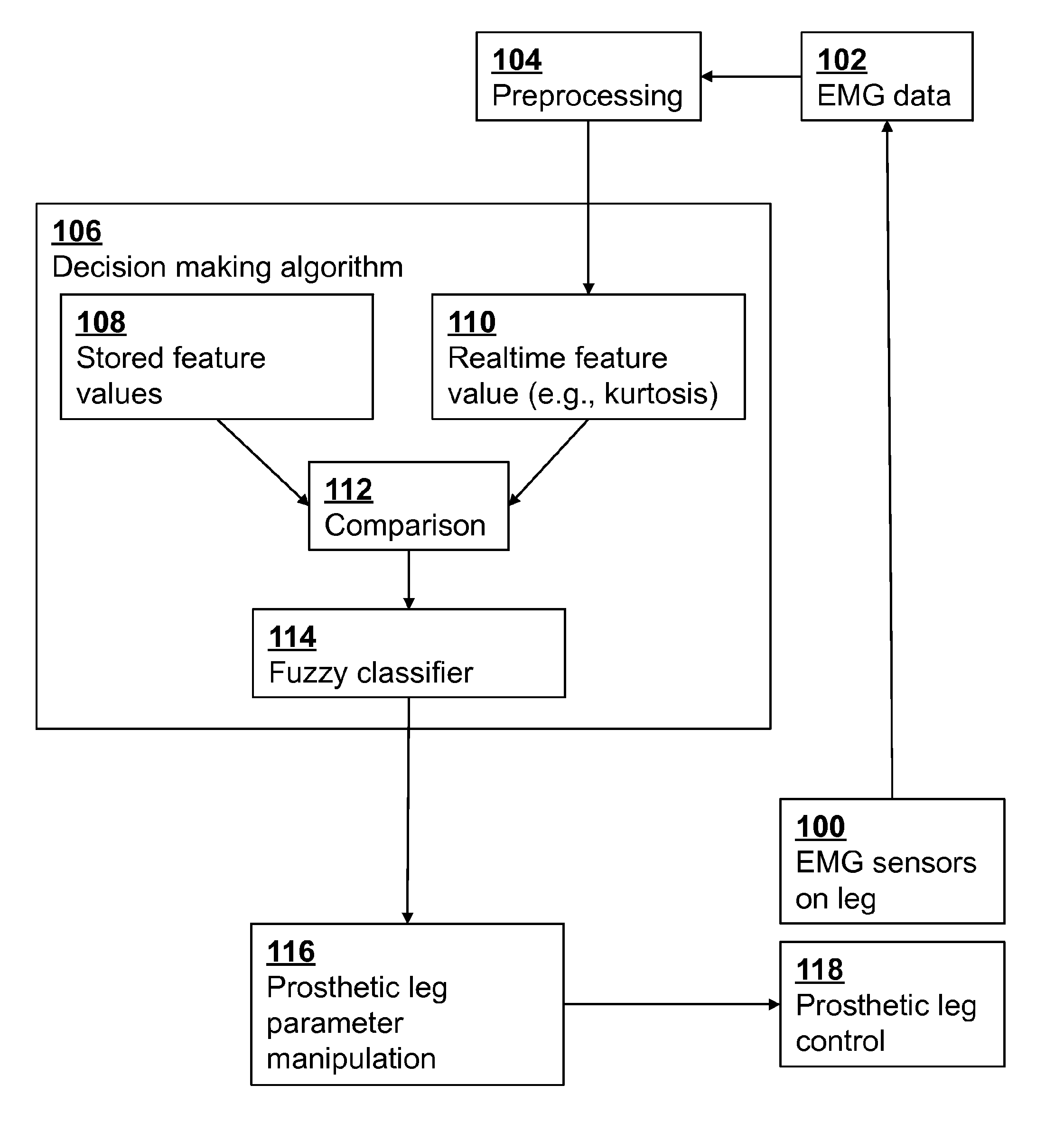
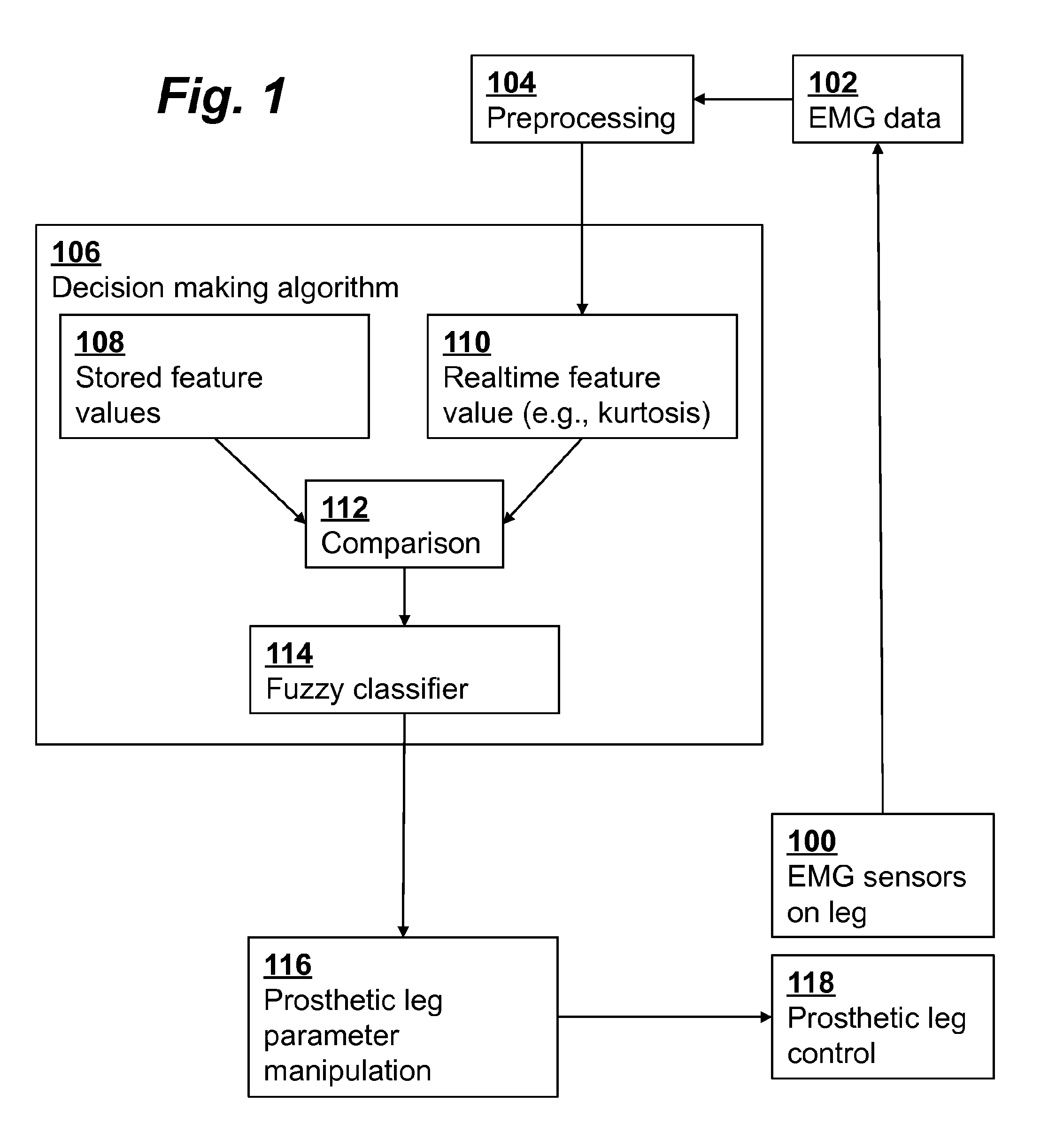
The invention is about using higher order moments of a spectrogram-induced histogram to identify different signals patterns associated with different walking phases, such as level walking, stair ascent / descent, and ramp ascent / descent. This allows for real-time control of transitions between different locomotion states and can be easily integrated into existing powered prosthetic / orthotic control platforms. Overall, the invention provides a simplified and effective approach for controlling powered prosthesis and orthotic devices.

Problems solved by technology

Current control strategies within the FSM approach do not allow amputees a seamless and natural transition between locomotion modes.

Method used


Image

  • Powered prosthetic devices using EMG-based locomotion state classifier
  • Powered prosthetic devices using EMG-based locomotion state classifier
  • Powered prosthetic devices using EMG-based locomotion state classifier

Examples


case 1

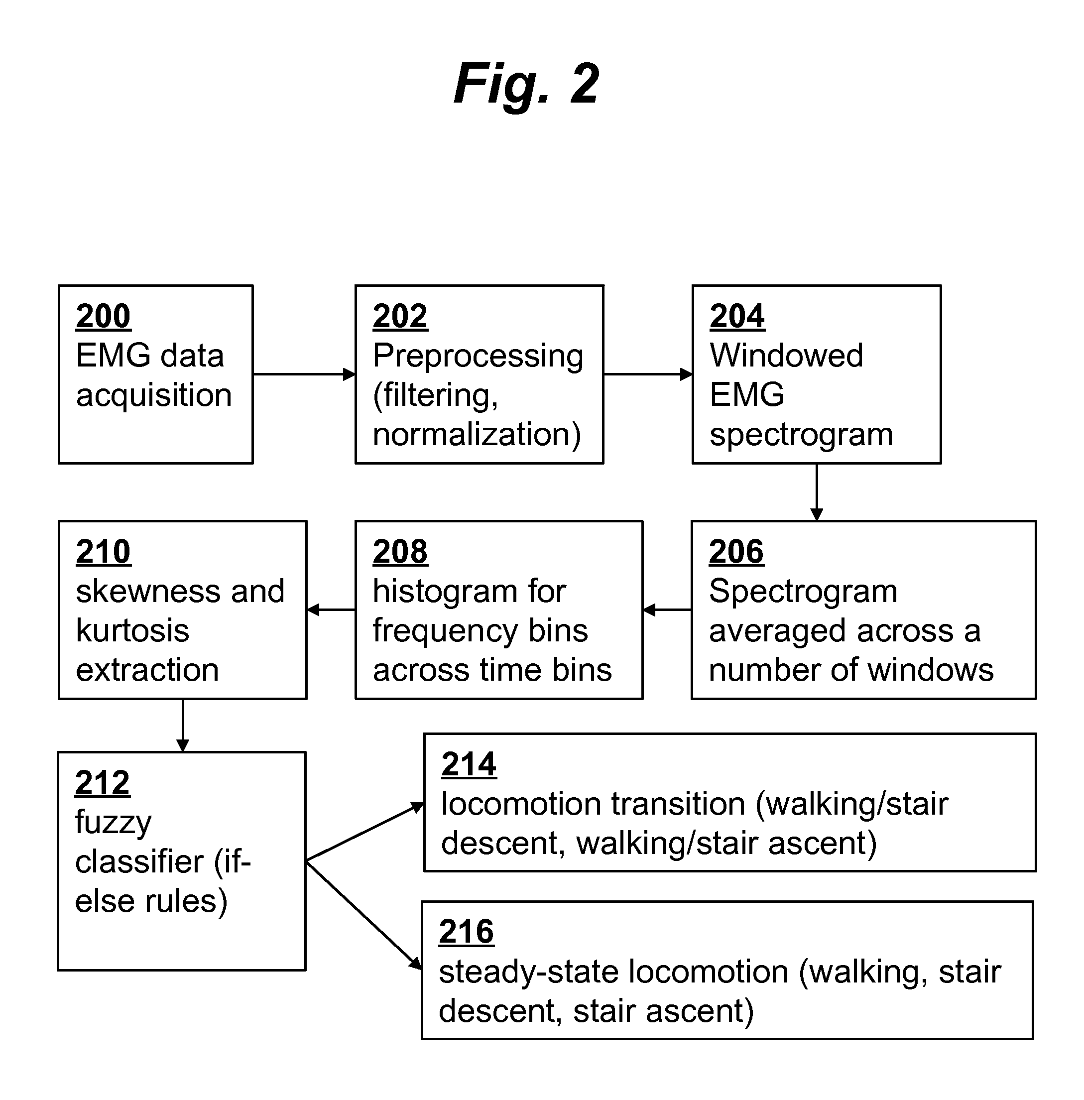
[0042] For locomotion transition state C1, the if-else rules are as follows:

[0043]If (k1−K) is LOW and (k2−K) is HIGH, then select class c1 (GL to SD).

[0044]If (k1−K) is HIGH and (k2−K) is LOW, then select class c2 (GL to SA).

[0045]For other transitions we will have similar k terms from training data which are stored in the microprocessor. For example k6 for GL to RA (Ramp Ascent). Accordingly, the rules can be designed to facilitate the additional k terms. Here we show an example for SA and SD as representative transitions. The number of rules will increase as the number of transition types increase.

case 2

[0046] For locomotion steady state C2, the if-else rules are as follows:

[0047]If (k3−K) is LOW and (k4−K) is HIGH and (k5−K) is HIGH, then select class c3 (GL).

[0048]If (k3−K) is HIGH and (k4−K) is LOW and (k5−K) is HIGH, then select class c4 (SA).

[0049]If (k3−K) is HIGH and (k4−K) is HIGH and (k5−K) is LOW, then select class c5 (SD).

[0050]The weighting strength for each rule is defined by F(Rule)=μ(LOW)*μ(HIGH).

[0051]In effect, the two-step classification helps increase computational efficiency of the classification.

[0052]In another embodiment, classification may be performed using matching scores (MS) and then discriminating functions in the form of if-else rules. For example, if Sk is the stored histogram for class k where k is W, W to SA, or SA, then for real time data spectrogram, T, the matching score MSk for a class k may be defined as follows:

MSk=Σm=1, 7 Σi=1, M Σj=1, N Sk(i, j, m)*Ti, j, m

where i and j are the time and frequency bin index, respectively, and m is the index ...


PUM


Abstract

Real-time control of a prosthetic device using EMG-based locomotion state classification computes a histogram [208] of a time-frequency spectrogram [206] of the EMG data [200] sampled from muscles, classifies the histogram using if-else rules [212] as representing a locomotion steady state [216] or locomotion transition state [214] in the prosthetic device, and controls the prosthetic device using the computed transitions between locomotion modes. The classification may be based on a comparison of feature values [210] derived from the histogram and stored feature values derived from histograms of known locomotion states. Alternatively, the classification may be based on matching scores calculated from the histogram and stored histograms of known locomotion states. The classifying preferably is performed using hierarchical if-else fuzzy classification rules [212], and may further include using a prior locomotion state and a state diagram specifying constraints on locomotion states accessible from other locomotion states.

Description

FIELD OF THE INVENTION[0001]The present invention relates generally to the field of prosthetics. More specifically, it relates to improved control techniques for powered prosthetic devices.BACKGROUND OF THE INVENTION[0002]To restore the locomotion capabilities of lower limb amputees many prosthetic legs have been developed. Most of the commercially available lower limb prostheses are either passive or powered devices controlled with finite-state machine (FSM) approaches. Current control strategies within the FSM approach do not allow amputees a seamless and natural transition between locomotion modes. Therefore, there is a need for a strategy which can predict the intended locomotion task and transition ahead of time to achieve the desired damping, allowing safe and smooth locomotion transitions.SUMMARY OF THE INVENTION[0003]In one aspect, the invention provides a method for real-time detection of transitions between locomotion modes or states using muscle activation signals as inpu...

Claims


Application Information

Patent Timeline
Patent Type & Authority Applications(United States)
IPC IPC(8): A61F2/72A61B5/0488A61B5/11
CPCA61F2/72A61B5/04888A61B5/1126A61B5/1123A61F2/60A61B5/7264G16H50/20A61B5/389A61F2002/704
Inventor HAHN, MICHAELJOSHI, DEEPAK
Owner UNIVERSITY OF OREGON
Learn More