
Double belt press apparatus

a press apparatus and belt technology, applied in the field of double belt press apparatus, can solve the problems of limited use of conventional fiber reinforced composite materials in space aviation and expensive vehicles, and the obstacle to expanding the use of continuous fiber reinforced composite materials

Inactive Publication Date: 2016-06-02
HYUNDAI MOTOR CO LTD +1
View PDF4 Cites 1 Cited by
  • Summary
  • Abstract
  • Description
  • Claims
  • Application Information

AI Technical Summary

Benefits of technology

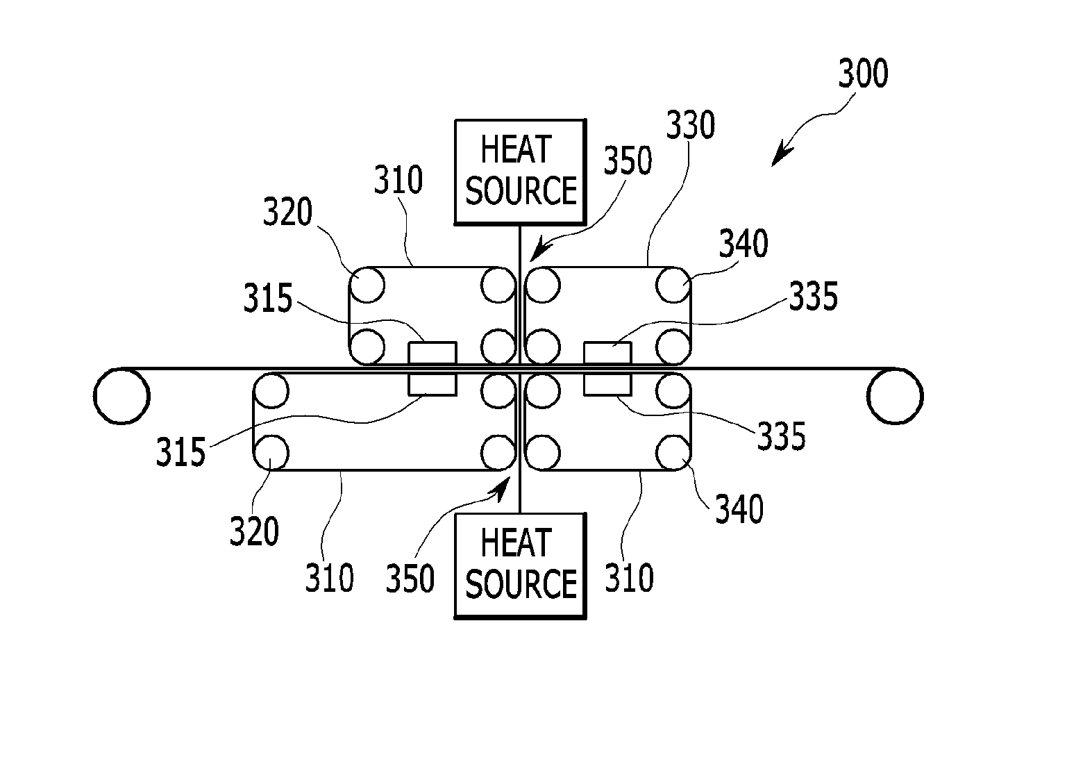
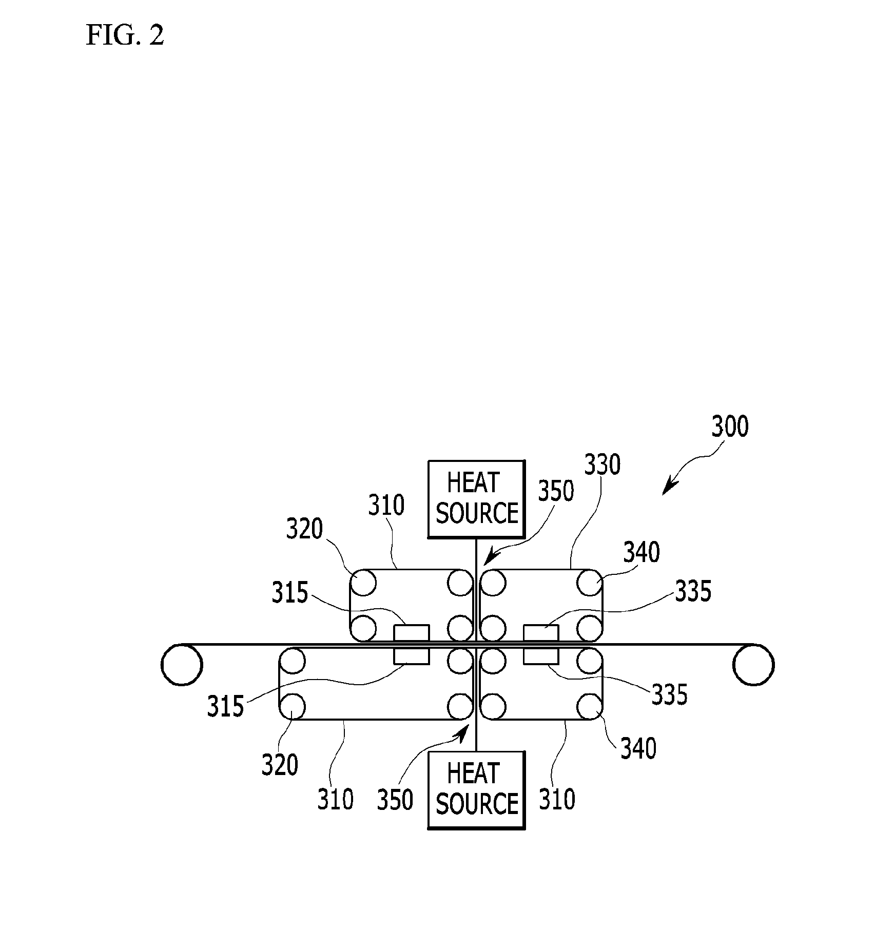
The present invention is about a double belt press apparatus that can control the temperature of a self-reinforcing composite material precisely and evenly during the shaping process. The apparatus includes two separate press sections for temperature control, and a pressure maintaining jig to keep the pressure uniform when the material is conveyed. The technical effect is a more accurate and uniform shaping of the composite material.

Problems solved by technology

However, while it is possible to use a continuous fiber-reinforced composite material as a structural element which may replace existing metals owing to a physical property reinforcing effect thereof, conventional use of continuous fiber-reinforced composite materials is limited to space aviation and expensive vehicles due to its high cost resulting from low productivity and low recyclability.
Further, there a problem can arise when applying the continuous fiber-reinforced composite material to an exterior panel of a vehicle, since achieving an excellent surface characteristic is difficult due to a difference of shrinkages between the fiber and a base material, creating an obstacle for expanding use of the continuous fiber-reinforced composite material.

Method used


Image

  • Double belt press apparatus
  • Double belt press apparatus
  • Double belt press apparatus

Examples


Embodiment Construction

[0027]The present disclosure will be described more fully hereinafter with reference to the accompanying drawings, in which embodiments of the disclosure are shown. As those skilled in the art would realize, the described embodiments may be modified in various different ways, all without departing from the spirit or scope of the present disclosure.

[0028]Parts not relevant to the present disclosure will be omitted for describing the present disclosure clearly, and throughout the specification, identical or similar parts will be given the same reference numbers. Further, since sizes and thicknesses of elements are shown at will for convenience of description, the present disclosure is not limited to the drawings without fail, but the thicknesses are enlarged for clearly expressing different parts and regions.

[0029]The terminology used herein is for the purpose of describing particular embodiments only and is not intended to be limiting of the disclosure. As used herein, the singular f...


PUM

PropertyMeasurementUnit
temperatureaaaaaaaaaa
pressureaaaaaaaaaa
frictionaaaaaaaaaa

Abstract

Disclosed is a double belt press apparatus including one pair of front double belts arranged on an upper side and a lower side of a fiber material, respectively, being continuously supplied thereto to rotate in opposite directions and pressing the fiber material from the upper side and the lower side while conveying the fiber material, at least three front conveying rollers moving the front double belts, one pair of rear double belts arranged on a downstream side of the front double belts on an upper side and a lower side of the fiber material, respectively, being continuously supplied thereto to rotate in opposite directions and pressing the fiber material from the upper side and the lower side while conveying the fiber material, at least three rear conveying rollers moving the rear double belts, and a pressure maintaining jig provided between the front double belts and the double belts applying a predetermined pressure to the fiber material being conveyed from the front double belts to the rear double belts.

Description

CROSS-REFERENCE TO RELATED APPLICATION[0001]This application claims priority to and the benefit of Korean Patent Application No. 1 0-201 4-01 68285 filed in the Korean Intellectual Property Office on Nov. 28, 2014, the entire contents of which are incorporated herein by reference.BACKGROUND[0002](a) Technical Field[0003]The present disclosure relates generally to a double belt press apparatus. More particularly, the present disclosure relates to a double belt press apparatus which enables precise and uniform temperature control at the time of fabrication of a self-reinforcing composite material.[0004](b) Description of the Related Art[0005]Composite materials have been recently developed which have the strength of a metal with the lightness and formability of a plastic. Notable composite materials with high strength and high elasticity include high-tech, reinforcing composite materials for lightweight structure, often composed of a fiber (e.g., carbon fiber). As an example, fiber re...

Claims


Application Information

Patent Timeline
Patent Type & Authority Applications(United States)
IPC IPC(8): B29C35/02B29C70/04B29C70/42
CPCB29C35/0288B29C70/42B29C70/04B29K2907/045B29K2301/12B29K2827/18B29K2101/12B29C70/40B29C70/54B30B5/06B29C2059/145B29C70/506B29C43/48B29C43/52B29C2043/483
Inventor KANG, HYUN MINYUN, DEOK WOO
Owner HYUNDAI MOTOR CO LTD
Learn More