
Inverter-Based Head End Power System

a power system and inverter technology, applied in the field of locomotives, can solve the problems of increased emissions, increased maintenance costs, and increased power output of the main engine of the locomotive, and achieve the effects of reducing and increasing the number of locomotives

Inactive Publication Date: 2016-05-26
ELECTRO-MOTIVE DIESEL
View PDF9 Cites 14 Cited by
  • Summary
  • Abstract
  • Description
  • Claims
  • Application Information

AI Technical Summary

Benefits of technology

This patent describes a head end power (HEP) system for a locomotive that includes two inverter modules that convert power from a DC link to an AC for the HEP bus. The system also includes a transformer and a HEP load that is distributed over the two inverter modules. The technical effect of this system is to provide a flexible and reliable power source for the passenger cars of the locomotive.

Problems solved by technology

If the HEP generator is a parasitic generator, the main engine of the locomotive may have to maintain a higher power output and fuel consumption.
If the HEP generator operates independently of the main engine, then the use of a separate system may translate into higher maintenance costs.
In addition, both types of HEP generators produce undesirable noise levels and require additional fuel consumption, which leads to increased emissions.

Method used


Image

  • Inverter-Based Head End Power System
  • Inverter-Based Head End Power System
  • Inverter-Based Head End Power System

Examples


Embodiment Construction

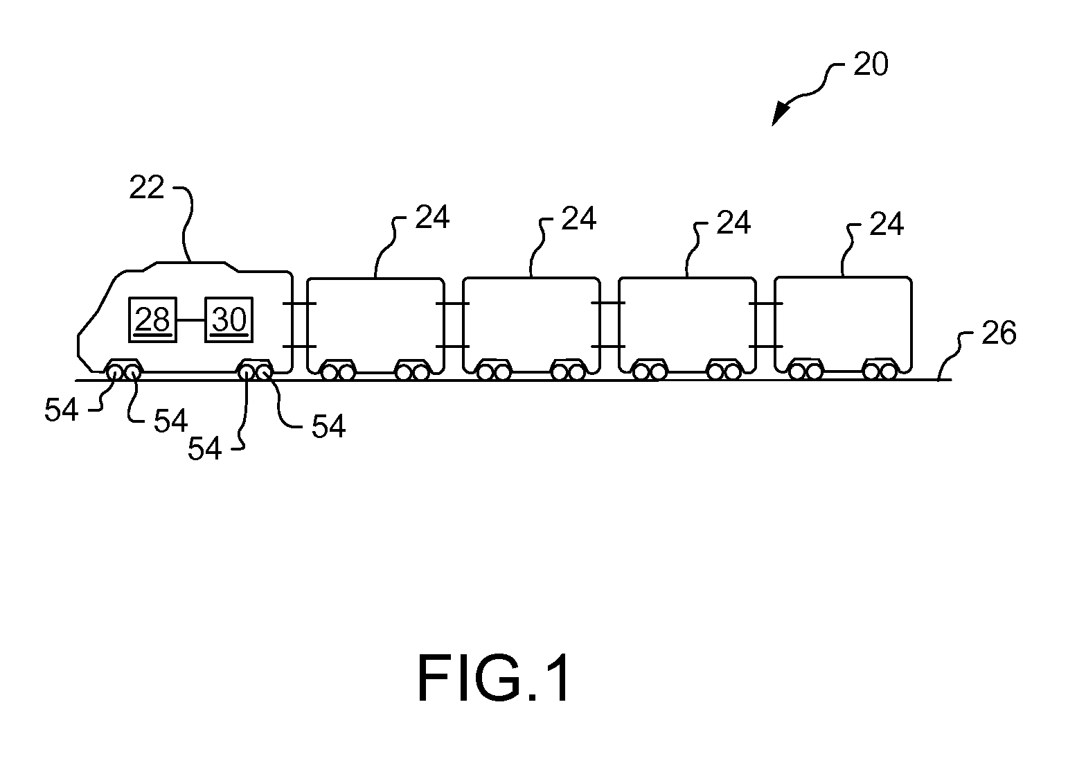
[0026]The present disclosure provides an inverter-based system and method for providing head end power (HEP) in a locomotive. The HEP system and method provide at least two inverter modules in parallel between a direct current (DC) link and a transformer. The transformer of the HEP system and method allows the inverter modules to be paralleled, while generating a single output onto a HEP bus. The HEP bus then delivers the necessary power to the various loads of the HEP system. Furthermore, the DC link input to the parallel inverter modules is supplied by the primary power source, or main alternator / generator. In so doing, a separate HEP generator is not needed for the disclosed system and method. By eliminating a second generator, the inverter-based HEP system and method significantly reduce noise levels, fuel consumption, and emission levels in locomotives, while still providing the requisite HEP to passenger train cars,

[0027]Reference will now be made in detail to specific embodim...


PUM


Abstract

A head end power (HEP) system for a locomotive is disclosed. The HEP system may include a first HEP inverter module operatively connected between a direct current (DC) link and a transformer, and a second HEP inverter module operatively connected between the DC link and the transformer in parallel with the first HEP inverter module. The first HEP inverter module and the second HEP inverter module may be configured to convert power from the DC link into an alternating current (AC). The transformer may be configured to transfer power from the first HEP inverter module and the second HEP inverter module to a HEP bus.

Description

FIELD OF THE DISCLOSURE[0001]The present disclosure relates generally to locomotives and, more particularly, head end power systems for locomotives.BACKGROUND OF THE DISCLOSURE[0002]Freight trains and passenger trains generally include a locomotive that provides the motive power for a train. Having no payload capacity of its own, the sole purpose of the locomotive is to move the train along the tracks. Typically, the locomotive may use an engine to drive a primary power source, such as, a main generator or an alternator. Converting mechanical energy into electrical energy, the primary power source provides power to traction motors in order to drive wheels of the locomotive. The traction motors propel the train along the tracks.[0003]Unlike freight cars, passenger cars of a train require electrical power for various applications unrelated to propulsion or locomotion. For example, passenger cars may require electrical power for heating, cooling, ambient lighting, and energizing electr...

Claims


Application Information

Patent Timeline
IPC IPC(8): B61C7/00B60L1/00
CPCB60L1/00B61C7/00B60L1/003B60L1/06B60L1/14B60L3/003B60L3/04B60L15/007B60L15/20B60L2200/26B60L2210/30B60L2210/40B60L2220/42B60L2240/12B60L2240/421B60L2240/423B60L2240/441B60L2240/443B60L2250/16B61C5/00B60L50/13Y02T10/64Y02T10/72Y02T30/00Y02T10/70
Inventor JALLA, MADAN
Owner ELECTRO-MOTIVE DIESEL
Learn More