
Hinge device

a technology of a hinge and a hinge body, which is applied in the direction of portable computer details, electrical apparatus casings/cabinets/drawers, instruments, etc., can solve the problems of flexible display breakage and the hinge device, and achieve the effect of preventing the damage of an object whose allowable curvature is restrained relative to the bending

Inactive Publication Date: 2016-05-19
SENEKA
View PDF0 Cites 94 Cited by
  • Summary
  • Abstract
  • Description
  • Claims
  • Application Information

AI Technical Summary

Benefits of technology

This patent describes a hinge device that allows for the secure mounting of objects on rotating parts. The hinge device has a continuous surface that is connected to both parts, providing support for objects that need to be secured across a section. Additionally, the hinge device can form a surface using multiple cover blocks, ensuring that the length of objects mounted on the parts remains unchanged. Furthermore, the hinge device allows for bending along an arc, preventing damage to objects with a certain level of flexibility.

Problems solved by technology

Meanwhile, unlike the display device according to prior art, a hinge device may create a problem when a recently-favored flexible display is installed in an area capable of covering both the first body unit and the second body unit.
That is, the flexible display may be excessively folded beyond a bending deflection limit sustainable by the flexible display, at a border area between the first body unit and the second body unit where the hinge device is mounted, and length may be changed when the hinge device is rotated to disadvantageously generate a breakage possibility of the flexible display due to receipt of compressive force power or tension.

Method used


Image

  • Hinge device
  • Hinge device
  • Hinge device

Examples


Embodiment Construction

[0027]Various exemplary embodiments will be described more fully hereinafter with reference to the accompanying drawings, in which some exemplary embodiments are shown.

[0028]In describing the present disclosure, certain layers, sizes, shapes, components or features may be exaggerated for clarity and convenience. Accordingly, the meaning of specific terms or words used in the specification and claims should not be limited to the literal or commonly employed sense, but should be construed or may be different in accordance with the intention of a user or an operator and customary usages. Therefore, the definition of the specific terms or words should be based on the contents across the specification.

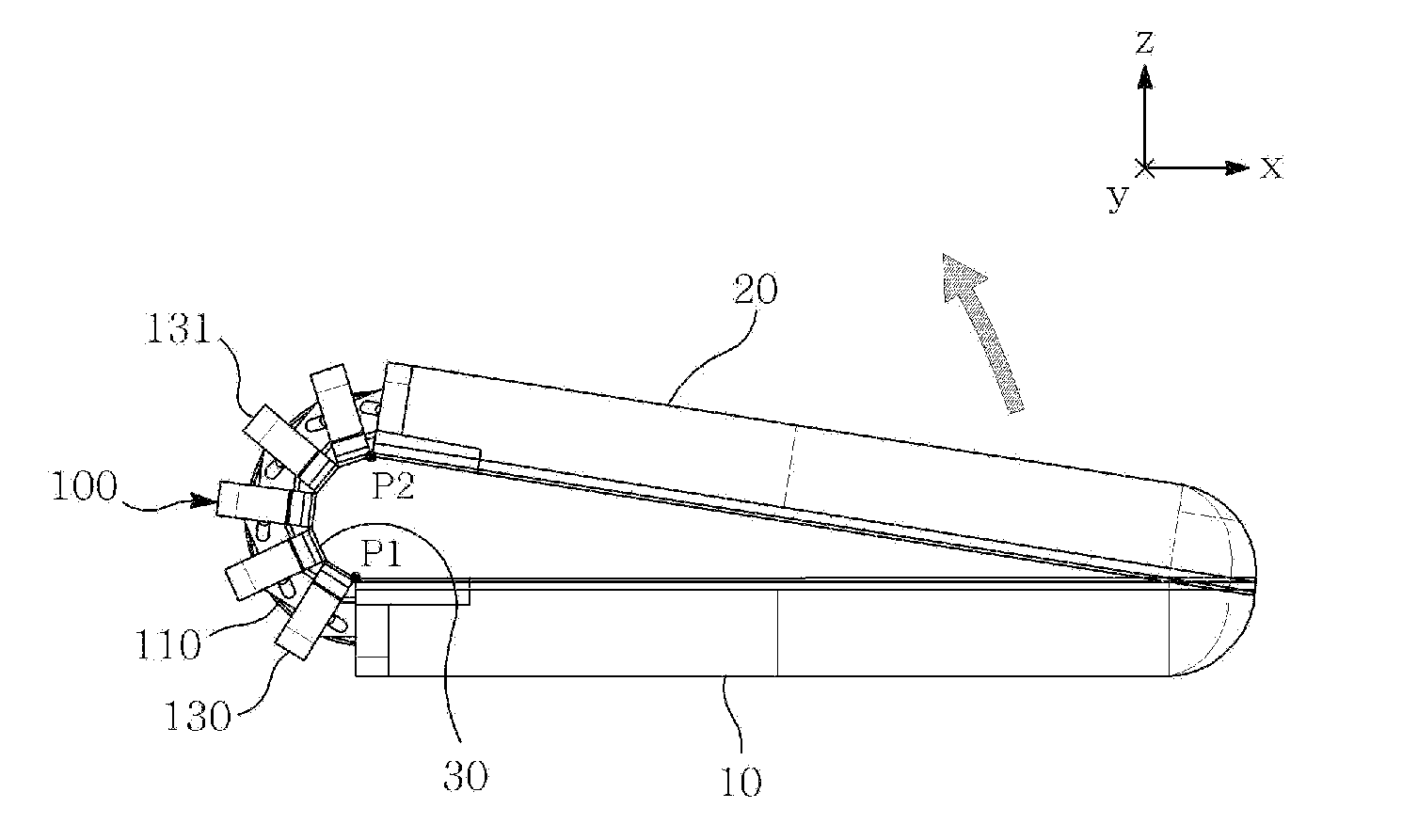
[0029]FIG. 1 is a schematic view illustrating a hinge device according to the present disclosure.

[0030]The hinge device illustrated in FIG. 1 may include a hinge unit (100).

[0031]The hinge device according to the present disclosure may include a support means which becomes a rotation center...


PUM


Abstract

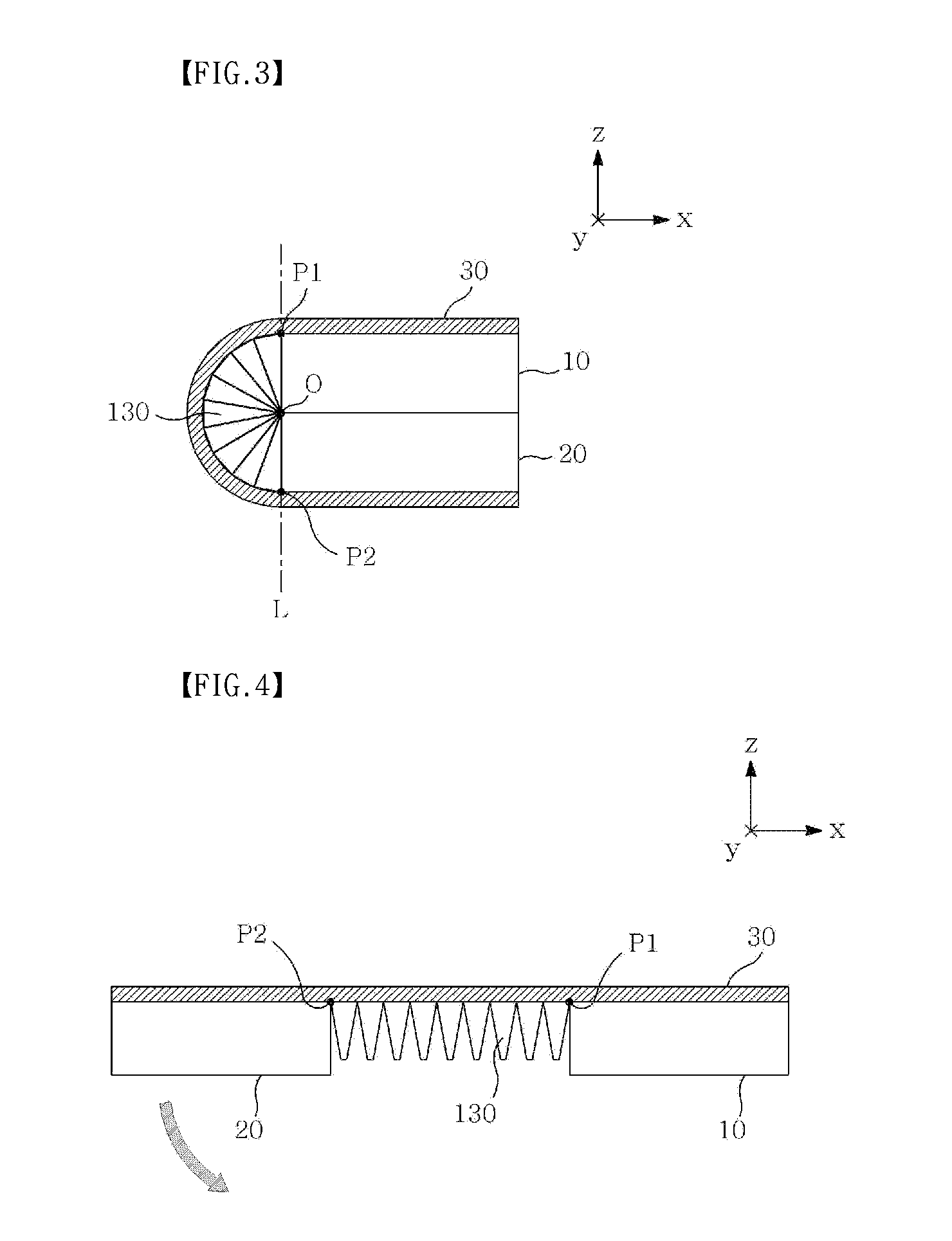
The hinge device according to the present disclosure may include a hinge unit configured to mutually and rotatably connect a first member and a second member, and a first surface of the hinge unit may be continued to at least one surface of a first particular surface of the first member and a second particular surface of the second member.

Description

[0001]Pursuant to 35 U.S.C. §119 (a), this application claims the benefit of earlier filing date and right of priority to Korean Patent Application No. 10-2014-0161666, filed on Nov. 19, 2014, the contents of which are hereby incorporated by reference in their entirety.BACKGROUND OF THE DISCLOSURE[0002]1. Field[0003]The teachings in accordance with the exemplary embodiments of this present disclosure generally relate to a hinge device configured to connect separately-arranged two members in a rotatable manner.[0004]2. Background[0005]Multiple media devices such as notebooks and mobile phones are generally configured in a folder-type. A notebook is generally configured in a folder type capable of opening and closing a first body unit mounted with a main board and a key board, and a second body unit mounted with a display screen. At this time, a hinge device is mounted at a rotation center between the first body unit and the second body unit.[0006]Meanwhile, unlike the display device ...

Claims


Application Information

Patent Timeline
IPC IPC(8): G06F1/16E05D7/00
CPCG06F1/1652E05D7/00G06F1/1681F16C11/04F16C11/12F16C2314/00E05D3/06G06F1/1616E05Y2999/00
Inventor CHO, PIL JEHUH, YOUNG WOO
Owner SENEKA
Learn More