
Air intake system for an off-road vehicle

a technology for air intake systems and off-road vehicles, which is applied in the direction of combustion-air/fuel-air treatment, electric control, separation processes, etc., can solve the problems of significant air intake demands, dirt and dust may be present in relatively high concentrations, and the pre-cleaners of the typical air intake system for off-road vehicles may not suitably filter the incoming air

Active Publication Date: 2016-05-19
BLUE LEAF I P
View PDF4 Cites 12 Cited by
  • Summary
  • Abstract
  • Description
  • Claims
  • Application Information

AI Technical Summary

Benefits of technology

The patent describes an air intake system for off-road vehicles that includes a pre-cleaner with tubes to filter out particulate matter from air. The system has a controller that receives a signal based on the engine's air intake flow rate and determines the number of open tubes needed for optimal performance. The controller then sends a signal to block the flow of air to the remaining tubes. The system also includes a cover that moves to direct airflow to the target number of tubes and prevent air from flowing to the remainder. The technical effect of the patent is an improved air intake system that optimizes air filtering performance and directs airflow for optimal engine performance.

Problems solved by technology

Engines of many off-road vehicles, such as trucks, tractors, combines, and other specialized vehicles for use in various construction or agricultural applications, have significant air intake demands.
In the challenging construction and agricultural environments in which such vehicles operate, dirt and dust may be present in relatively high concentrations.
However, the pre-cleaners of typical air intake systems for off-road vehicles may not suitably filter the incoming air.
Accordingly, the primary intake filter of typical air intake systems may become clogged with debris, resulting in reduced air flow to the engine and impaired engine performance.

Method used


Image

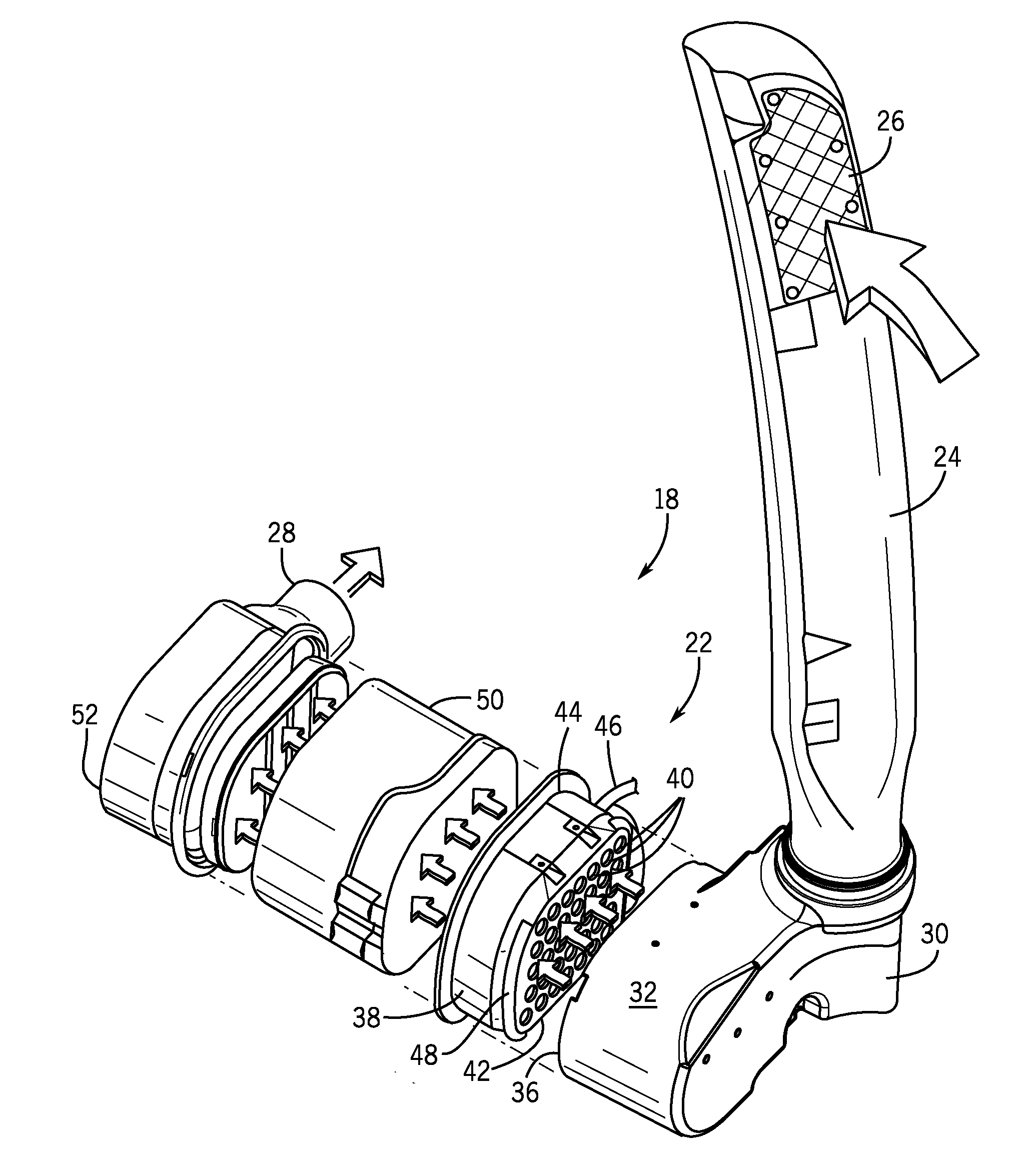
  • Air intake system for an off-road vehicle
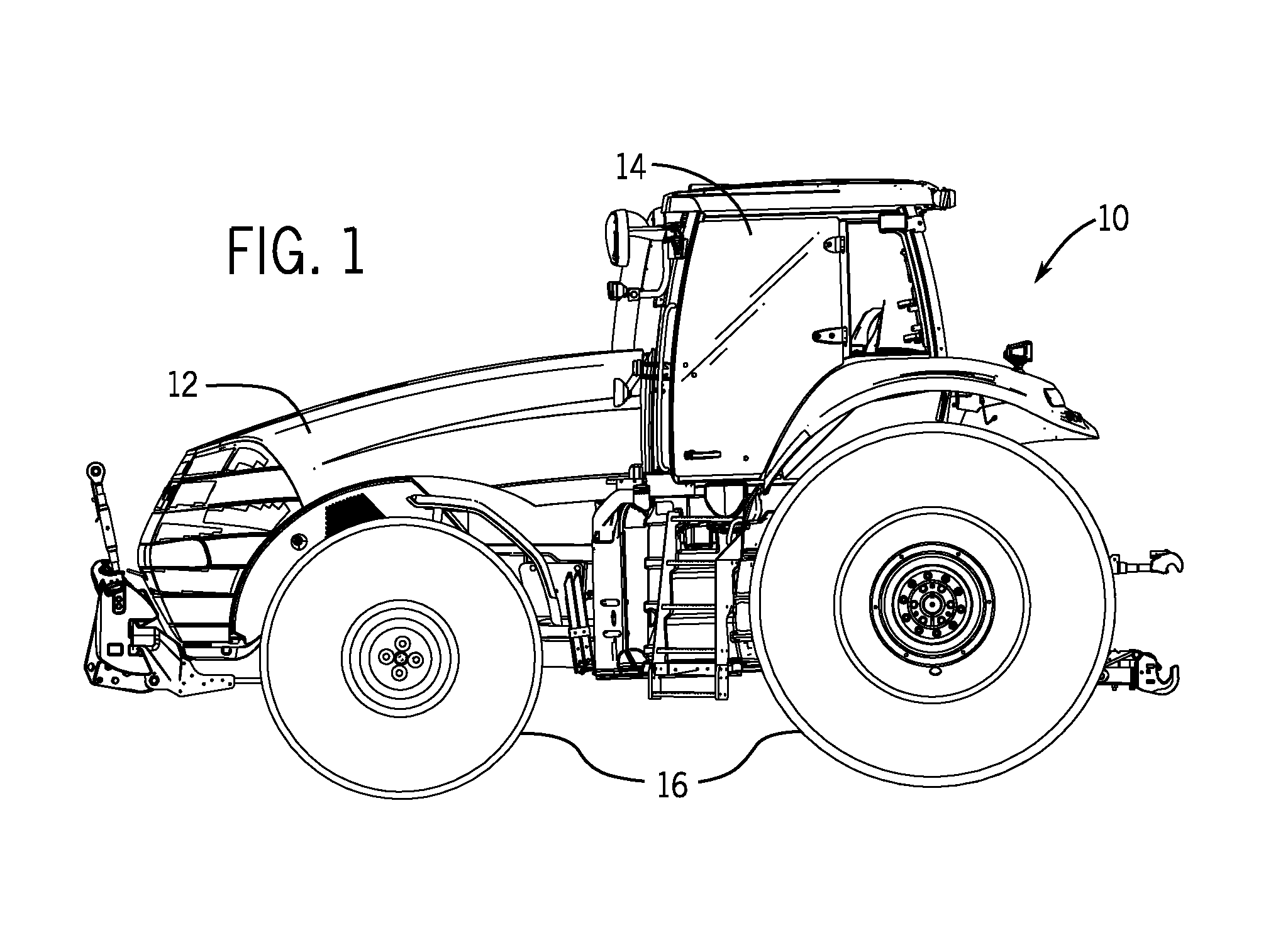
  • Air intake system for an off-road vehicle
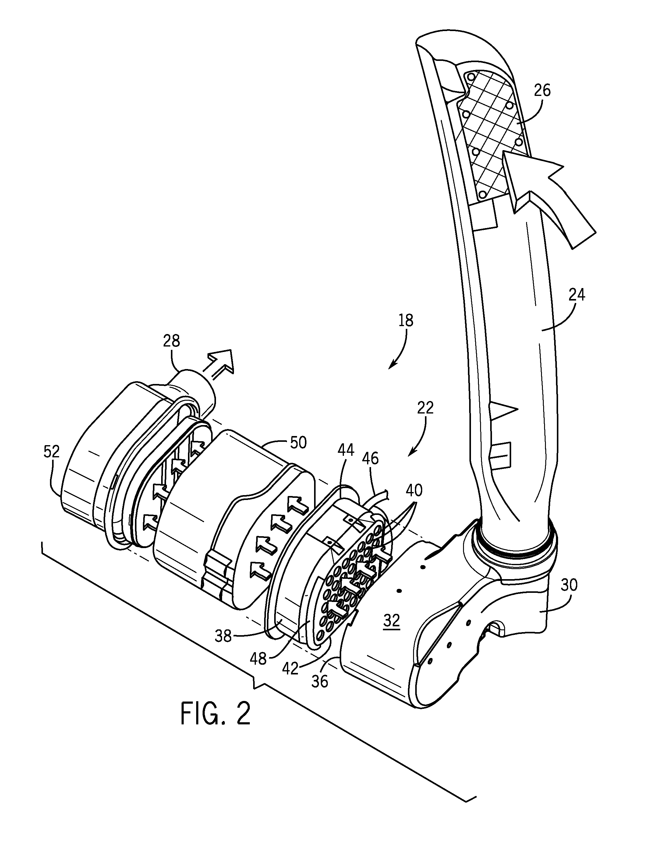
  • Air intake system for an off-road vehicle

Examples


Embodiment Construction

[0014]One or more specific embodiments of the present disclosure will be described below. In an effort to provide a concise description of these embodiments, all features of an actual implementation may not be described in the specification. It should be appreciated that in the development of any such actual implementation, as in any engineering or design project, numerous implementation-specific decisions must be made to achieve the developers' specific goals, such as compliance with system-related and business-related constraints, which may vary from one implementation to another. Moreover, it should be appreciated that such a development effort might be complex and time consuming, but would nevertheless be a routine undertaking of design, fabrication, and manufacture for those of ordinary skill having the benefit of this disclosure.

[0015]When introducing elements of various embodiments of the present disclosure, the articles “a,”“an,”“the,” and “said” are intended to mean that th...


PUM

PropertyMeasurementUnit
Flow rateaaaaaaaaaa

Abstract

An air intake system includes a pre-cleaner having a plurality of tubes configured to receive a flow of air, to filter particulate material from the flow of air, and to provide the flow of air to an engine of an off-road vehicle. The system also includes a controller configured to receive a first signal indicative of an air intake flow rate of the engine, to determine a target number of open tubes for the pre-cleaner based at least in part on the air intake flow rate and a desired air flow rate for each tube of the plurality of tubes, and to output a second signal to a component of the air intake system indicative of instructions to enable the flow of air to the target number of open tubes and to block the flow of air to the remainder of tubes of the plurality of tubes.

Description

BACKGROUND[0001]The present application relates generally to air intake systems, and more specifically, to a pre-cleaner of an air intake system and methods for controlling air flow through the pre-cleaner of the air intake system.[0002]Engines of many off-road vehicles, such as trucks, tractors, combines, and other specialized vehicles for use in various construction or agricultural applications, have significant air intake demands. In the challenging construction and agricultural environments in which such vehicles operate, dirt and dust may be present in relatively high concentrations. Accordingly, an air intake system having a series of filters is typically provided to filter incoming air upstream of the engine. Such air intake systems may include a pre-cleaner in series with a primary intake filter. The pre-cleaner may remove large particulate matter from the air, while the primary intake filter may remove finer particulate matter. However, the pre-cleaners of typical air intak...

Claims


Application Information

Patent Timeline
IPC IPC(8): F02D41/18F02M35/16F02M35/10F02M35/02F02M35/024
CPCF02D41/18F02M35/0209F02M35/0204F02M35/164F02M35/10262F02M35/10386F02M35/02416B01D45/12F02M35/10255F02M35/162F02M35/0205F02M35/0216F02D41/0002F02M35/0223F02M35/0215F02M35/084Y02T10/12Y02T10/40B01D50/20
Inventor KLASSEN, MARK DOUGLASGOMEZ, LORENZO ANTHONY
Owner BLUE LEAF I P
Learn More