
Locking regulation device for drawer slide rail

a technology for locking regulation and slide rails, which is applied in the direction of construction fastening devices, building locks, construction, etc., can solve the problems of not being able to meet user needs,

Inactive Publication Date: 2016-05-12
GUANGDONG TAIMING METAL PROD
View PDF4 Cites 19 Cited by
  • Summary
  • Abstract
  • Description
  • Claims
  • Application Information

AI Technical Summary

Benefits of technology

The present utility model provides a locking regulating device for drawer slide rail with simple and reasonable structure, easy assembly, reliable performance, extensive application, convenient disassembly and assembly, three-dimensional regulation function and high market adaptability. It allows for self-locking through lock catch, unlocking and separation of drawer and movable rail quickly and easily. The regulating mechanism can make up / down, left / right and front / back regulation to the relative position between drawer and movable rail, and coordinate the position of drawer to facilitate the user's opening and closing action and meet different users' needs.

Problems solved by technology

Since this structure is only provided with high-low regulating mechanism and thus is far from being able to meet the user needs.

Method used


Image

  • Locking regulation device for drawer slide rail
  • Locking regulation device for drawer slide rail
  • Locking regulation device for drawer slide rail

Examples


Embodiment Construction

[0028]Further detailed description of the present utility model is provided with reference to specific embodiments in combination with attached drawings.

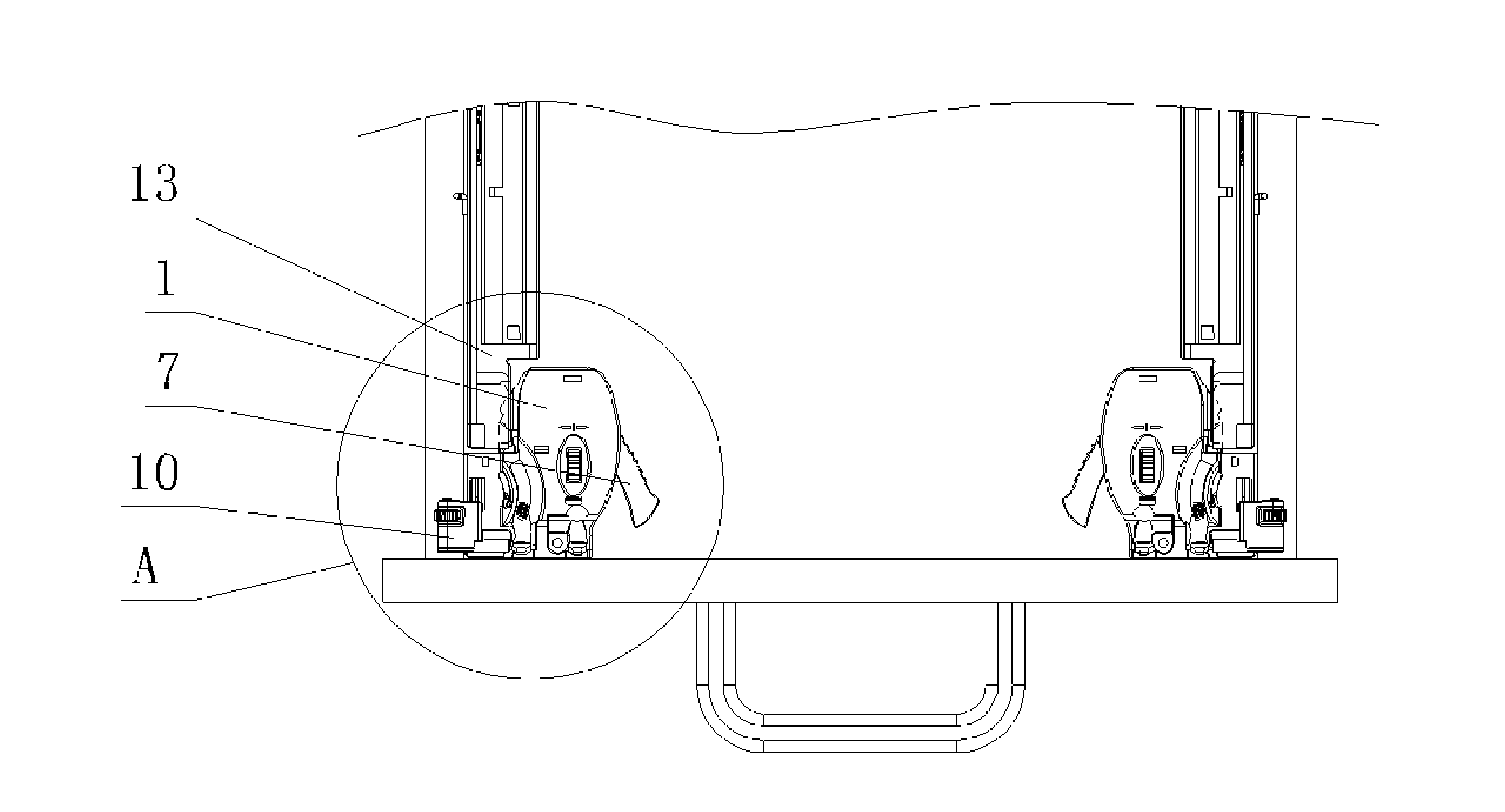
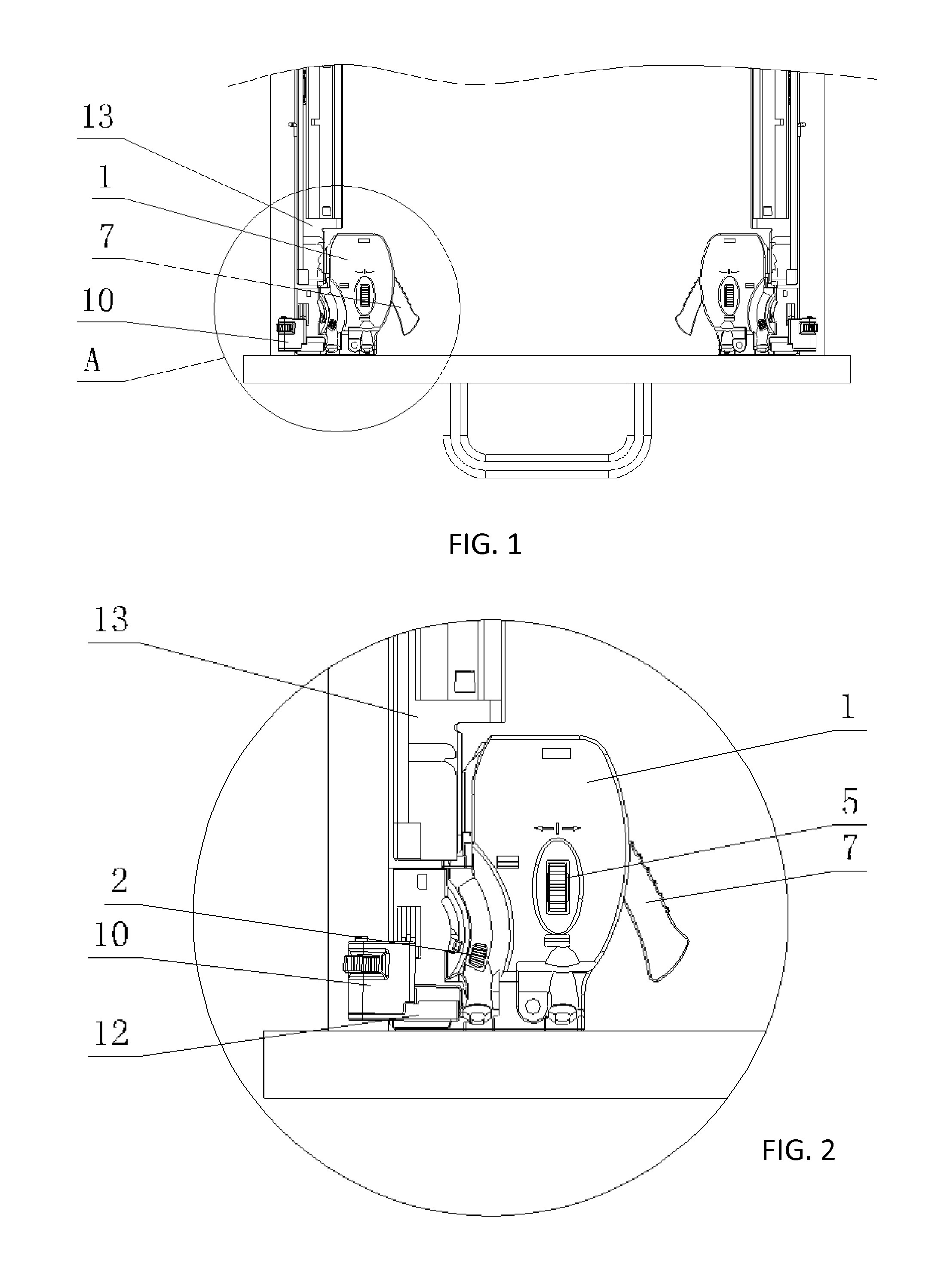
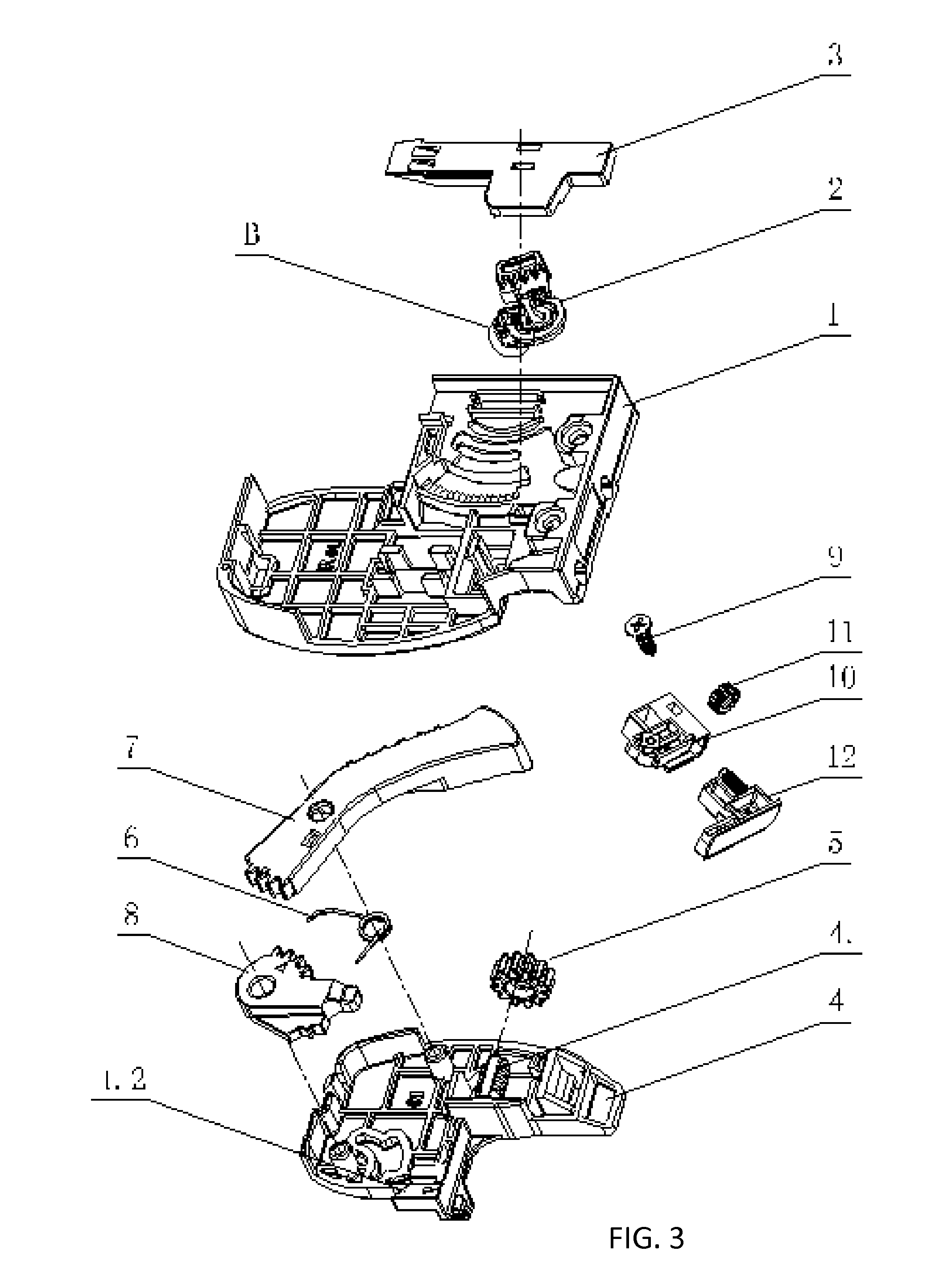
[0029]As shown in FIGS. 1-5, The locking regulating device for drawer slide rail, comprising a slide rail component and a drawer, wherein slide rail component is composed of a fixed rail fixed on the cabinet body and a movable rail 13 provide above the fixed rail, and the drawer is fixedly connected with the movable rail 13; a locking regulating device fixed on the drawer is also included, the drawer is designed to lock the square hole on the movable rail (13) through the locking regulating device, so as to realize mutual connection; a locking mechanism and a regulating mechanism are included in the locking regulating device; the locking mechanism is composed of a handle 7 and a lock catch 8 through mutual transmission; through the lock catch 8, the locking regulating device is self-locked on the movable rail and acts on the handle ...


PUM


Abstract

A locking regulating device for drawer slide rail, comprising a slide rail component and a drawer, wherein the drawer is fixedly connected with the movable rail on the slide rail component, characterized in that, a locking regulating device fixed on the drawer is also included, the drawer is designed to latch the square hole on the movable rail through the locking regulating device to realize mutual connection; the locking regulating device comprises a locking mechanism and a regulating mechanism; the locking mechanism is composed of a handle and a lock catch through mutual transmission; through the lock catch, the regulating device is self-locked on the movable rail and acts on the handle to complete unlocking of the lock catch; the regulating mechanism is designed to respectively make three-dimensional regulation to the drawer from up / down, left / right and front / back directions. The present utility model realizes locking and three-dimensional regulation through the locking mechanism and the regulating mechanism. The locking mechanism is designed to realize self-locking by locking the movable rail through lock catch and perform unlocking through handle transmission to lock catch, so as to conveniently realize the unlocking and separation between drawer and movable rail. The regulating mechanism is designed to respectively make regulation to the drawer in the up / down, left / right and front / back direction, thus contributes to the coordination between drawer and movable rail and meets the demand of different consumers.

Description

FIELD OF THE INVENTION[0001]The present utility model relates to a locking device for drawer and slide rail, in particular to a locking regulating device for drawer and slide rail.BACKGROUND OF THE PRIOR ART[0002]On Apr. 10, 2013, Chinese patent document (CN 102326978 B) discloses a locking regulating mechanism for drawer slide rail, comprising a coupling base for drawer bottom surface, a locking lever is rotationally connected on the connecting base, a latch bolt in buckled connection with slide rail is provided on one end of the locking bar, another end of locking bar extents out of the handle, the latch bolt is disengaged from the slid rail by pressing the handle. An inclined guidance plane is provided on the slide rail corresponding to the latch bolt, a stepped type locking part is provided at the back of the guidance plane, the stepped type locking part is in buckled connection with the locking hole provided on the slide rail, the quantity of steps of the stepped type locking p...

Claims


Application Information

Patent Timeline
Patent Type & Authority Applications(United States)
IPC IPC(8): A47B88/16E05C3/16E05C3/22A47B88/04E05B65/46A47B88/427
CPCA47B88/16A47B88/04E05C3/165E05C3/22E05B65/46A47B88/427A47B2088/4274
Inventor NG, TAI WAI
Owner GUANGDONG TAIMING METAL PROD
Learn More