Diagnosis system for pulsed plasma

a pulsed plasma and diagnostic system technology, applied in the direction of pulse technique, optical radiation measurement, instruments, etc., can solve the problem that the basic characteristics of pulsed plasma have not been determined

Active Publication Date: 2016-05-05
SAMSUNG ELECTRONICS CO LTD
View PDF0 Cites 14 Cited by
  • Summary
  • Abstract
  • Description
  • Claims
  • Application Information

AI Technical Summary

Problems solved by technology

However, due to lack of a diagnosis system capable of monitoring the characteristics of pulsed plasma formed by the pulsed RF power supply in current facilities, even the basic characteristics of pulsed plasma have not been determined so far.

Method used


Image

  • Diagnosis system for pulsed plasma
  • Diagnosis system for pulsed plasma
  • Diagnosis system for pulsed plasma

Examples


Embodiment Construction

[0039]Example embodiments will now be described more fully hereinafter with reference to the accompanying drawings; however, they may be embodied in different forms and should not be construed as limited to the embodiments set forth herein. Rather, these embodiments are provided so that this disclosure will be thorough and complete, and will fully convey exemplary implementations to those skilled in the art.

[0040]It will be understood that when an element or layer is referred to as being “on”, “connected to” or “coupled to” another element or layer, it can be directly on, connected or coupled to the other element or layer or intervening elements or layers may be present. In contrast, when an element is referred to as being “directly on”, “directly connected to” or “directly coupled to” another element or layer, there are no intervening elements or layers present. Meanwhile, spatially relative terms, such as “between” and “directly between” or “adjacent to” and “directly adjacent to”...


PUM

PropertyMeasurementUnit
RF frequencyaaaaaaaaaa

Abstract

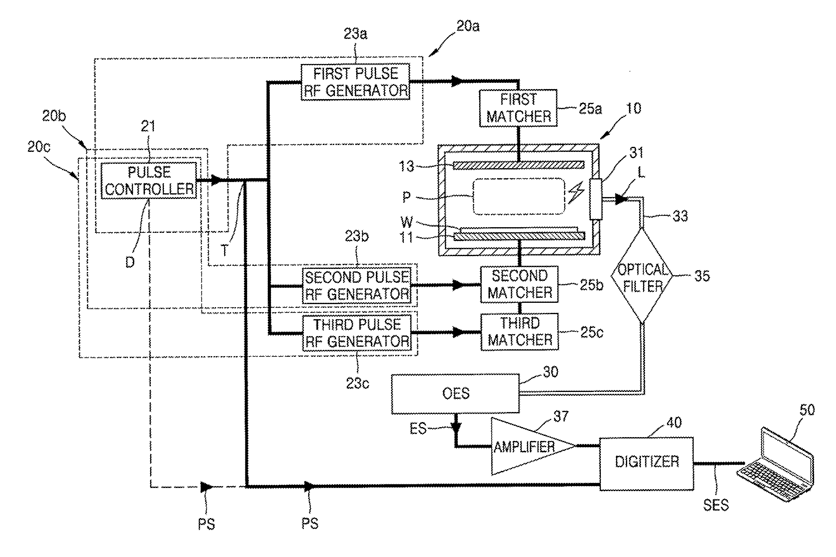
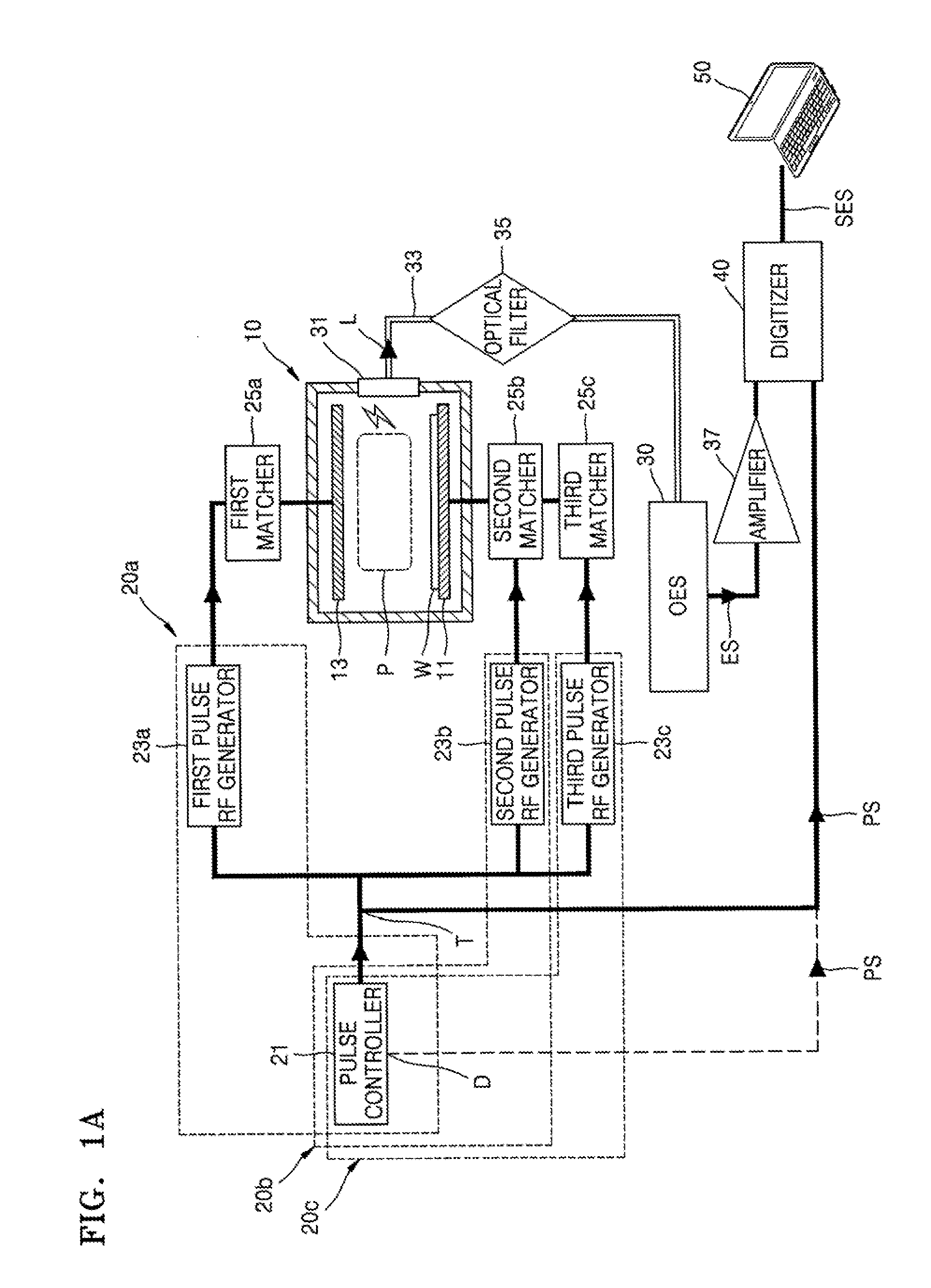
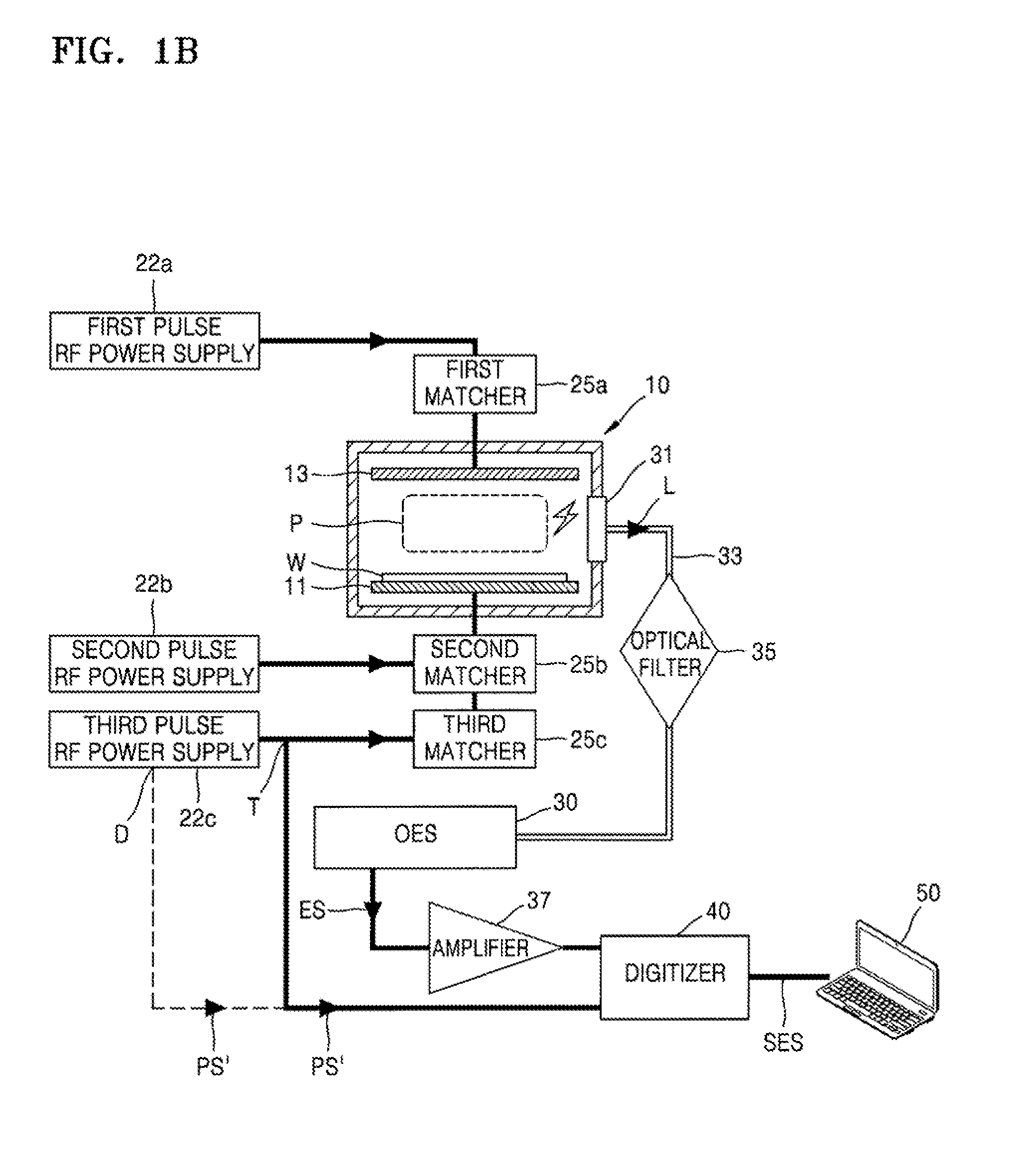
A diagnosis system for pulsed plasma includes an optical emission sensor (OES) to receive light generated the pulsed plasma, the pulsed plasma having been generated in accordance with a pulse signal, a digitizer to synchronize the electrical signal with the pulse signal, and an analyzer to analyze the synchronized electrical signal.

Description

CROSS-REFERENCE TO RELATED APPLICATION[0001]Korean Patent Application No. 10-2014-0152086, filed on Nov. 4, 2014, in the Korean Intellectual Property Office, and entitled: “Diagnosis System for Pulsed Plasma,” is incorporated by reference herein in its entirety.BACKGROUND[0002]1. Field[0003]Embodiments relate to a diagnosis system for pulsed plasma, and more particularly, to an optical emission sensor (OES) based diagnosis system for pulsed plasma.[0004]2. Description of the Related Art[0005]As semiconductor elements have been recently shrinking and made by laminating, a pulsed radio frequency (RF) power supply has been used instead of a continuous wave (CW) RF power supply in order to improve the selection ratio and profile in a deposition or etching process.[0006]However, due to lack of a diagnosis system capable of monitoring the characteristics of pulsed plasma formed by the pulsed RF power supply in current facilities, even the basic characteristics of pulsed plasma have not be...

Claims


Application Information

Patent Timeline
Patent Type & Authority Applications(United States)
IPC IPC(8): H01J37/32H01J37/244G01J1/44
CPCH01J37/32146H01J37/32926G01J2001/4238H01J37/244G01J2001/4453G01J1/44H01J37/32091H01J37/32935H01J37/32972H01J37/32082H01L21/3065H05H1/0006H05H1/0025
Inventor LEE, DONG-SOOJANG, SUNG-HOKIM, BYEONG-HEESUNG, DOUG-YONGSHIN, DONG-OK
Owner SAMSUNG ELECTRONICS CO LTD
Why Eureka
Try Eureka