
Image processing device, image processing method, and program

a technology of image processing and image processing method, applied in image enhancement, image analysis, instruments, etc., can solve the problems of increasing the size of the operation circuit portion, increasing the memory capacity necessary to temporarily store a plurality of images, and complicating the processing configuration

Active Publication Date: 2016-05-05
SONY SEMICON SOLUTIONS CORP
View PDF3 Cites 23 Cited by
  • Summary
  • Abstract
  • Description
  • Claims
  • Application Information

AI Technical Summary

Benefits of technology

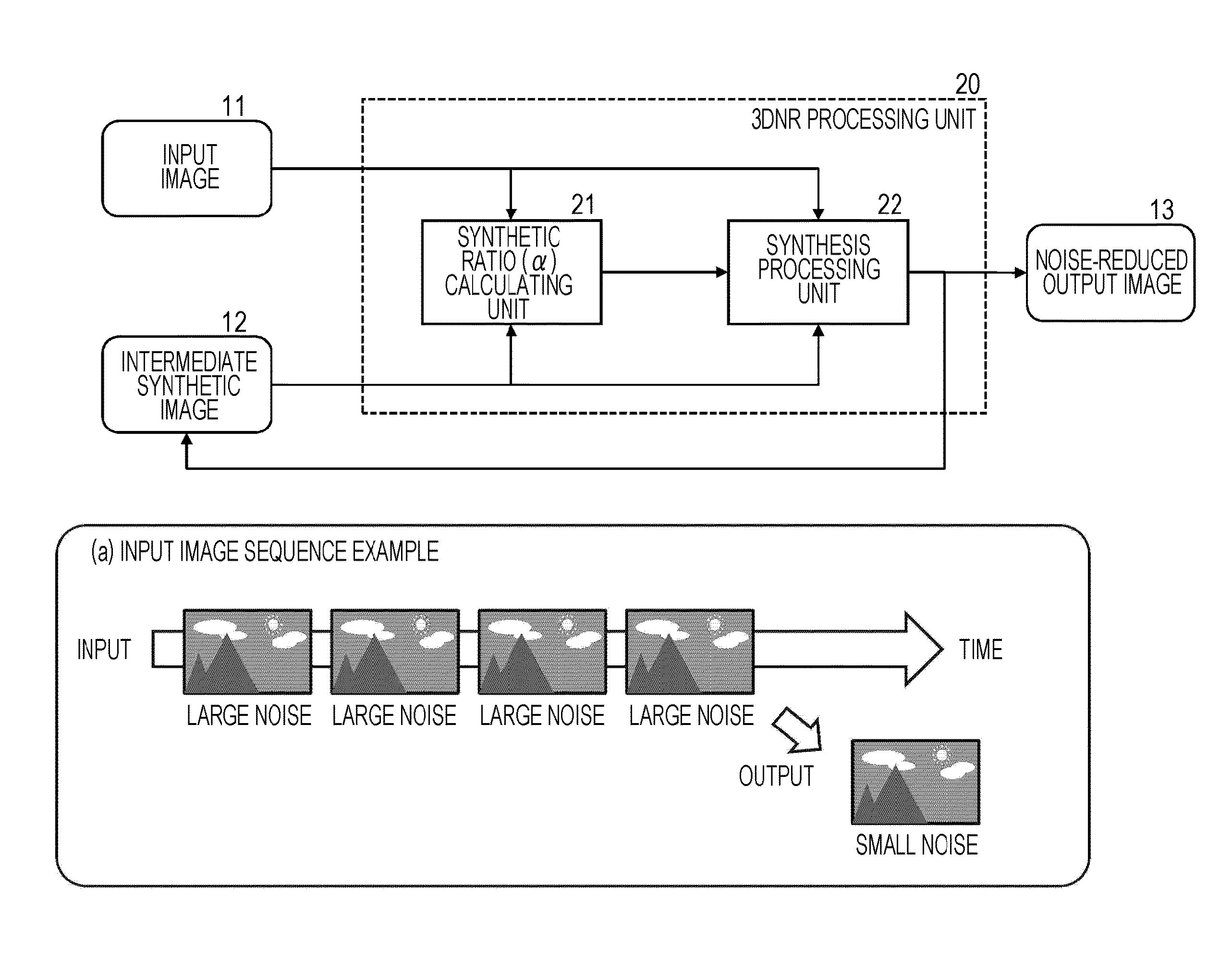
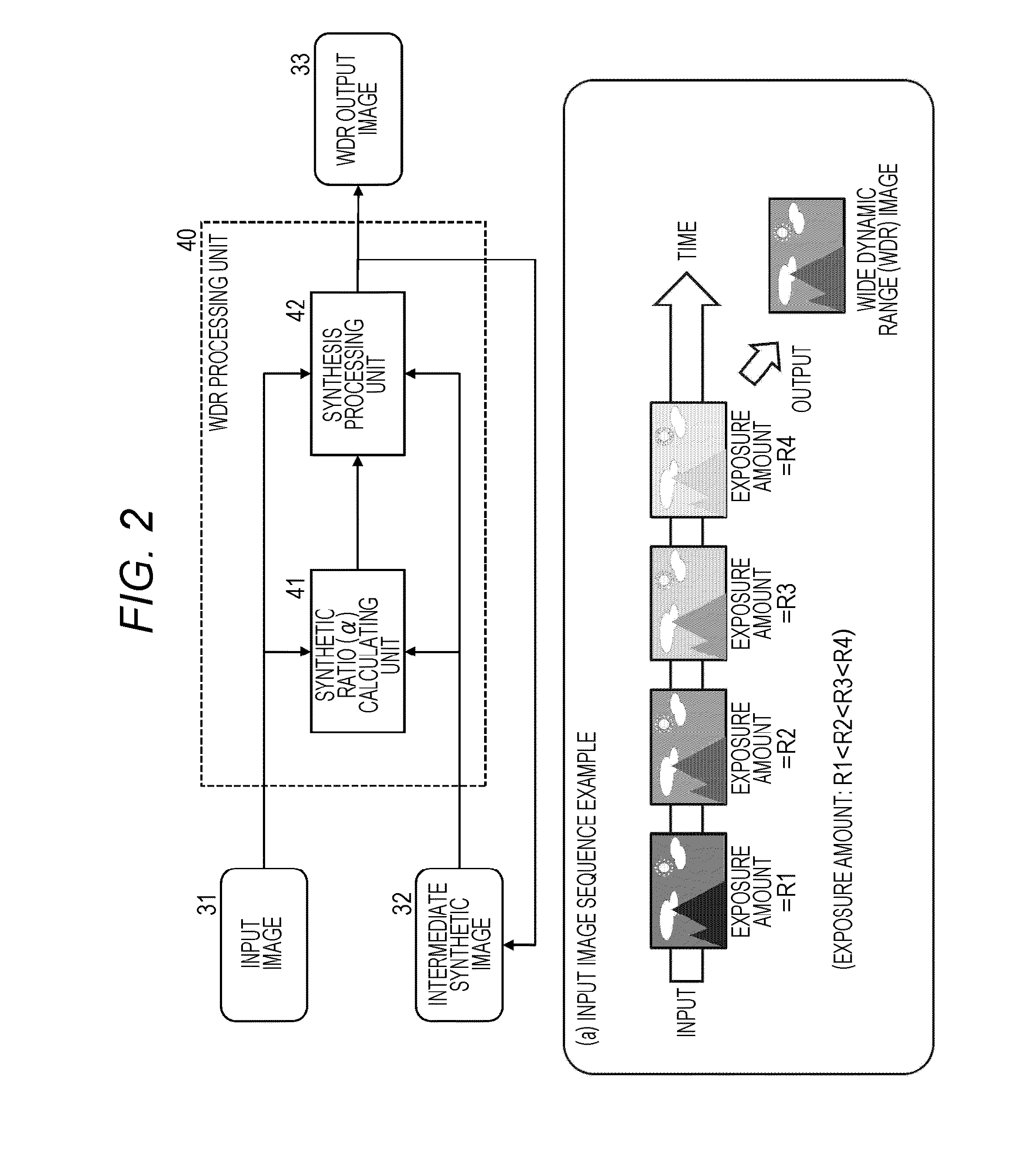
The present patent describes a method to generate an image with reduced noise and expanded dynamic range using a simple configuration. The method involves taking consecutive images with different exposures and identifying noise, effective, and saturation pixels in each image. The intermediate image is then synthesized based on the pixel classification results. The technique is capable of removing any residual noise from previous images and ensures improved quality of the resulting image.

Problems solved by technology

Here, a problem lies in that the 3DNR processing unit performing the noise reduction has to perform a synthesis using a plurality of images of the same exposure condition, and the WDR processing unit performing the wide dynamic range image generation has to perform a synthesis process of synthesizing a plurality of images of different exposure conditions.
In both of the configurations of FIGS. 3 and 4, there is a problem in that an operation circuit portion is increased in size since the synthesis process is independently performed, and a memory capacity necessary to temporarily store a plurality of images is increased.
In the configurations illustrated in FIGS. 3 and 4, the image synthesis process is performed without considering an alignment between images, but when an alignment is considered, a processing configuration is further complicated.
In the configuration in which an alignment between synthetic images is considered as illustrated in FIGS. 5 and 6, there is a problem in that compared to the configurations illustrated in FIGS. 3 and 4, a configuration is more complicated, and a size of hardware performing the above processes is increased.

Method used


Image

  • Image processing device, image processing method, and program
  • Image processing device, image processing method, and program
  • Image processing device, image processing method, and program

Examples


second embodiment

[0564]FIG. 22 is a block diagram illustrating the image update processing unit 124.

[0565]A difference of the image update processing unit 124 illustrated in FIG. 22 lies in that the output switching unit 152 of the image update processing unit illustrated in FIG. 21 is removed, and a selector 154 is provided.

[0566]The selector 154 receives the pixel unit update information 161 from the update method deciding unit 123, selects the synthesis result generated by the synthesis processing unit 153, that is, the synthetic pixel value serving as the synthesis process (3DNR) result of the corresponding pixels of the exposure-corrected input image and the intermediate synthetic image or the pixel value of the intermediate synthetic image 113 according to the pixel unit update information 161, and outputs the selected pixel value as the pixel value of the output image 115.

[0567]In other words, in the configuration illustrated in FIG. 22, for all pixels, the synthesis processing unit 153 selec...


PUM


Abstract

An image on which a noise reduction and a dynamic range expansion process have been performed is generated by a sequential synthesis process using continuous-photographed images of different exposure conditions. The continuous-photographed images of different exposure conditions are input, configuration pixels of an input image and an intermediate synthetic image are classified into a noise pixel, an effective pixel, or a saturation pixel, a synthesis processing method of a pixel unit is decided according to a combination of pixel classification results of the corresponding pixels, and the intermediate synthetic image is updated according to the decided method. A 3DNR process is performed when at least one of the corresponding pixels of the input image and the intermediate synthetic image is the effective pixel, the pixel value of the intermediate synthetic image is output without change when both of the corresponding pixels of the input image and the intermediate synthetic image are the saturation pixel or the noise pixel, and the 3DNR process is performed or the pixel value of the intermediate synthetic image is output when one is the saturation pixel, and the other is the noise pixel.

Description

TECHNICAL FIELD[0001]The present disclosure relates to an image processing device, an image processing method, and a program. Particularly, the present disclosure relates to an image processing device, an image processing method, and a program in which, for example, a noise reduction process or a dynamic range expansion process of an image is performed by a synthesis process of a plurality of images.BACKGROUND ART[0002]A synthesis process using a plurality of continuously photographed images is known to be effective as an image noise reduction (NR) process. Specifically, a pixel value in which noise is reduced is calculated by detecting a corresponding pixel serving as a photographing pixel region of the same subject from a plurality of continuously photographed images and performing, for example, a synthesis process of averaging pixel values of a plurality of corresponding pixels.[0003]A technique of performing noise reduction by continuously photographed images is a process using ...

Claims


Application Information

Patent Timeline
Patent Type & Authority Applications(United States)
IPC IPC(8): G06T5/00G06T7/00G06K9/62G06T5/50
CPCG06T5/002G06T5/50G06T2207/20216G06K9/6202G06K9/6267G06T7/003H04N1/409H04N1/387G06T2207/10144G06T2207/20208G06T2207/20221H04N23/741G06F18/24G06T5/70
Inventor TAKAHASHI, HIROAKIMITSUNAGA, TOMOOHANDA, MASAKIASAI, HARUKAYOSHIMURA, SHINSHIBATA, YASUSHI
Owner SONY SEMICON SOLUTIONS CORP
Learn More