
Self-powered solar illumination device with self-contained power system

a solar energy and power system technology, applied in semiconductor devices, lighting and heating apparatuses, with built-in power, etc., can solve the problem of not producing enough visibility in normal dayligh

Inactive Publication Date: 2016-05-05
GRIFFIN ANNE MARIE +1
View PDF0 Cites 1 Cited by
  • Summary
  • Abstract
  • Description
  • Claims
  • Application Information

AI Technical Summary

Benefits of technology

The patent describes a self-powered LED device that uses sunlight as its energy source. The device is durable, portable, water-resistant and compact. It can be used to illuminate a large room or transfer power to another device with a micro-USB port. It is equipped with solar panels to intake sunrays and conical shapes around the LEDs to emit light. The device has an interior on / off push switch to regulate the light intensity and a recharging mechanism. The device remains illuminated overnight and can be charged by USB.

Problems solved by technology

It did not produce enough visibility in normal daylight, and was used for military purposes and known as infrared LEDs.

Method used


Image

  • Self-powered solar illumination device with self-contained power system
  • Self-powered solar illumination device with self-contained power system
  • Self-powered solar illumination device with self-contained power system

Examples


Embodiment Construction

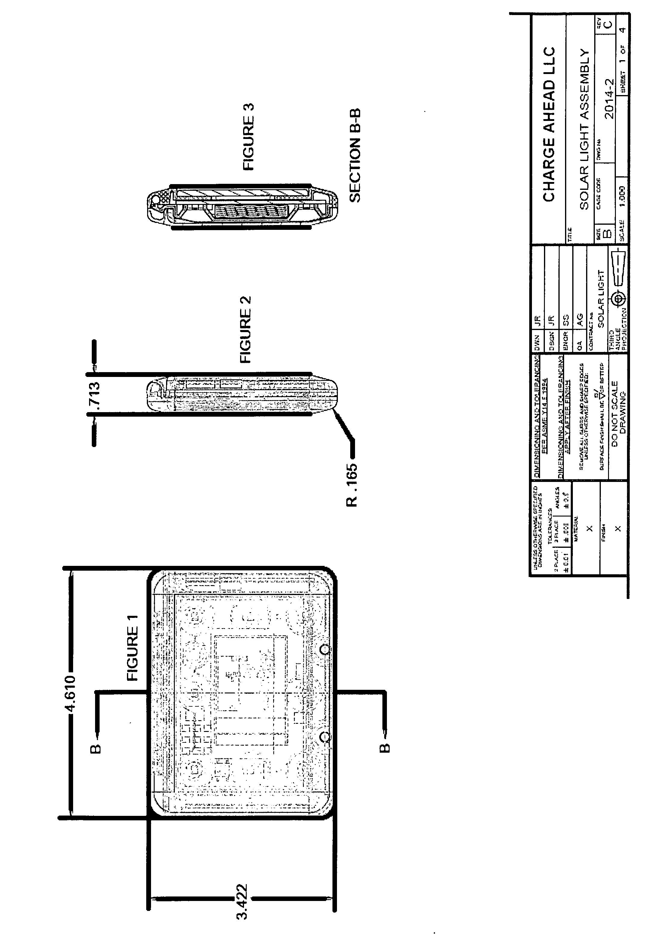
[0029]The solar powered illumination device includes an upper housing having an upper solar panel configured to receive solar light energy. A lower housing is attached with hinges to the upper housing defining a lower housing interior area in communication with the upper housing interior area. In die interior of housing contains a spring activated internal intensity settings switch to prevent accidental shutdown. Each LED is embedded in a case below a cone for protection and light diffusion. The top cover contains two (2) holes for hanging the device.

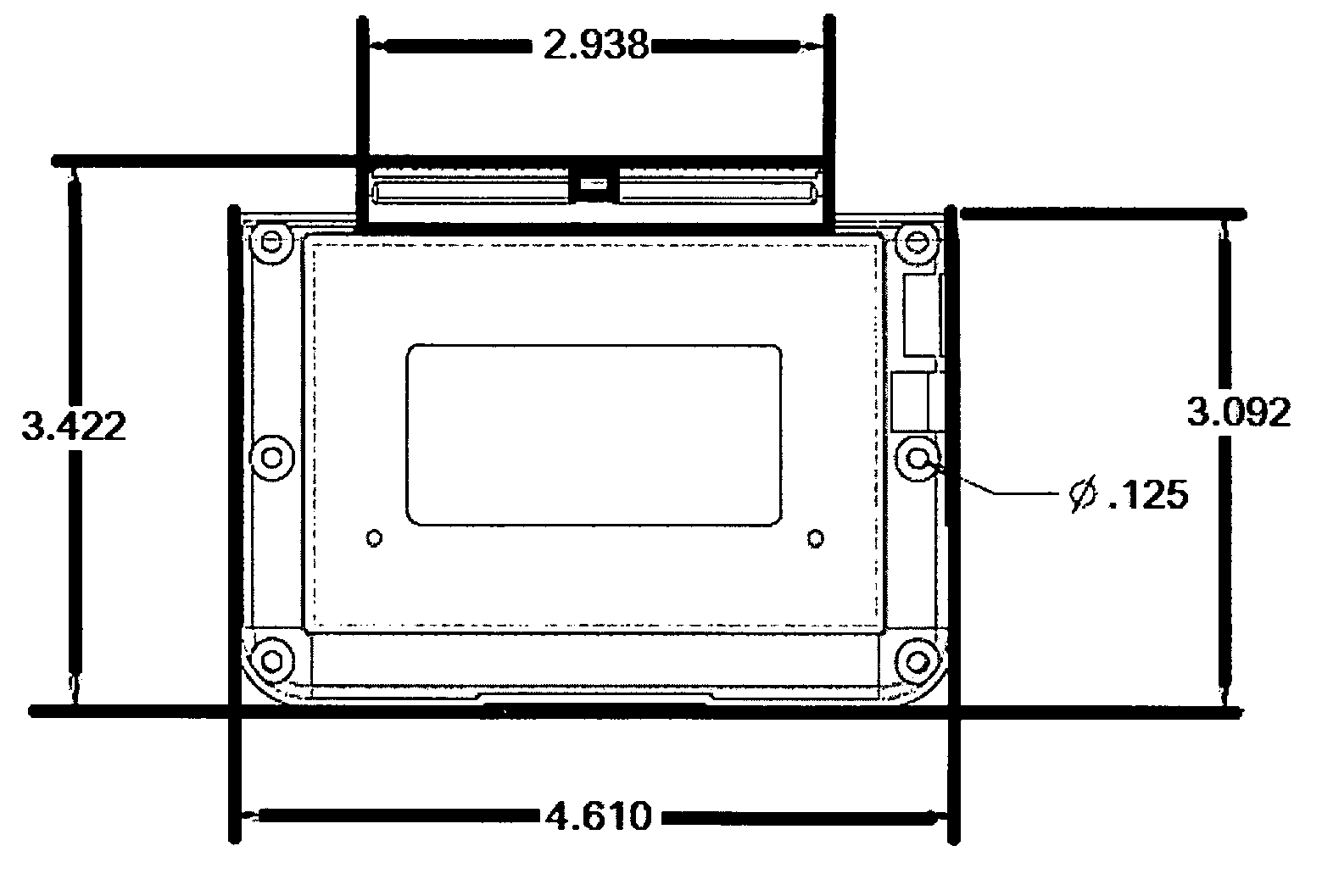
[0030]Sheet 1 of 4: Entire device center view with two (2) openings for a Multi-position switch and micro USB.

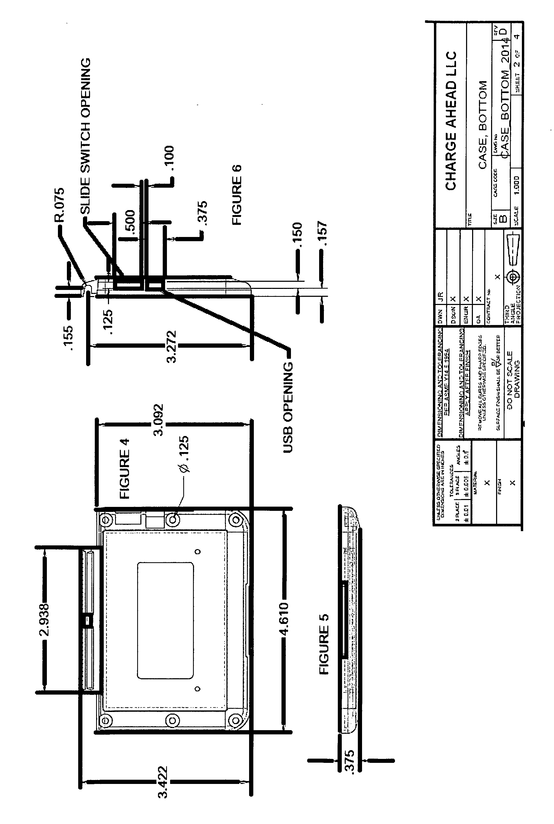
[0031]Sheet 2 of 4: Top, End A Right side view with 2 openings and dimensions.

[0032]Sheet 3 of 4: Top, End & Bisected view of PC Board heel that includes four (4) main dimensions of the conical shapes around the LEDs.

[0033]Diameter at top of cone—0.663 in

[0034]Diameter at bottom of cone—0.280 in

[0035]Height of cone—0.325 in

[0036...


PUM


Abstract

The quest for efficient lighting has been around for generations. LED (light emitting diode) is an efficient way to illuminate. Predecessors like the florescent light and standard incandescent light sources proved to only generate a fraction of the light source provided by a LED. Florescent light only provides a ¼ of a LED's illumination, and a standard incandescent light provides 1 / 20th of a LED's illumination. The self-powered device provides a compact, durable solution for efficient lighting through utilizing energy from the sun, as well as the potential to transfer solar energy to other small portable devices.

Description

REFERENCES CITED[0001]U.S. Patent Documents8,866,416October 2014Burrows, et al.8,858,015October 2014HarshawD715233October 2014Takao, et al.D715,731October 2014Nook, et al.8,866,407October 2014Takahashi8,853,947October 2014Asato8,853,953October 2014Pollock, et al.8,853,892October 2014Fells, et al.8,508,116August 2013Negley, et al.7,768,192August 2010Van De Ven, et al.7,008,078March 2006Shimizu, et al.6,817,735November 2004Shimizu, et al.5,803,579September 1998Turnbull, et al.May 17, 2012Sreshta, et al.Appl. 13 / 163,230Jul. 22, 2010Kugel, Jason,Appl. 12 / 356,733J / Scharles, Brian P.OTHER REFERENCES[0002]History of Solar Energy, Office of Energy Efficiency & Renewable Energy, www.energy.gov / eere[0003]M. Nisa Khan (Aug. 20, 2013) Understanding LED Illumination Hardcover[0004]Brian Clark Howard, Seth Leitmman, William Brinsky (Sep. 3, 2012) Green Lighting[0005]Solar Power (Apr. 8, 2012) Renewable Energy, What Are Solar Panels, What is Solar Power [Green Energy, What are Solar Panels][0006]A...

Claims


Application Information

Patent Timeline
Patent Type & Authority Applications(United States)
IPC IPC(8): F21S9/03F21V7/22F21V5/04F21V31/00F21S10/06F21S9/02
CPCF21S9/037F21S10/06F21S9/022F21Y2101/02F21V31/005F21V7/22F21V5/048F21V31/00F21L4/02H02J7/35F21Y2105/10F21Y2115/10H02J2207/40H02J7/00
Inventor GRIFFIN, ANNE MARIESMITH, STEPHEN JOSEPH
Owner GRIFFIN ANNE MARIE
Learn More