
Downhole distributed pressure sensor arrays, downhole pressure sensors, downhole distributed pressure sensor arrays including quartz resonator sensors, and related methods

a distributed pressure sensor and array technology, applied in the field of downhole distributed pressure sensor arrays, downhole pressure sensors, etc., can solve the problems of high heat requirement, optical fibers may fail to correctly transmit data, and optical fibers may be relatively fragile and prone to failure,

Active Publication Date: 2016-05-05
QUARTZDYNE
View PDF10 Cites 21 Cited by
  • Summary
  • Abstract
  • Description
  • Claims
  • Application Information

AI Technical Summary

Benefits of technology

This patent is about a downhole pressure sensor array that includes sensor housings with pressure sensors and chambers for holding fluid. The sensors are connected to each other by electrical conductors and cables. The technical effects of this invention include improved accuracy and reliability of pressure sensors in downhole environments, and the ability to detect pressure changes in real-time. Additionally, the invention provides a more efficient and cost-effective way to manufacture and operate downhole pressure sensors.

Problems solved by technology

However, optical fibers may fail to correctly transmit data if the fibers are bent (e.g., kinked) to a radius of curvature smaller than a certain fixed value, such value depending upon the fiber characteristics.
Furthermore, optical fibers may be relatively fragile and prone to failure under conditions where the fibers are subject to shock and vibration.
However, implementation of component bonding methods such as welding, which may provide a robust connection between components, may expose sensitive components of the sensor array to excessive, and potentially damaging, heat required by the welding process.
Further still, in situations where such arrays are implemented as arrays of pressure sensors, it may be required to at least partially expose the pressure sensors in the array to the pressure of the external environment (e.g., via a fluid within the sensor).
Thus, passing the electrical conductors past each pressure sensor may be difficult as such electrical conductors must be routed through or around portions of each sensor having housings that are equipped to handle the forces from pressures and temperatures of a downhole environment.

Method used


Image

  • Downhole distributed pressure sensor arrays, downhole pressure sensors, downhole distributed pressure sensor arrays including quartz resonator sensors, and related methods
  • Downhole distributed pressure sensor arrays, downhole pressure sensors, downhole distributed pressure sensor arrays including quartz resonator sensors, and related methods
  • Downhole distributed pressure sensor arrays, downhole pressure sensors, downhole distributed pressure sensor arrays including quartz resonator sensors, and related methods

Examples


Embodiment Construction

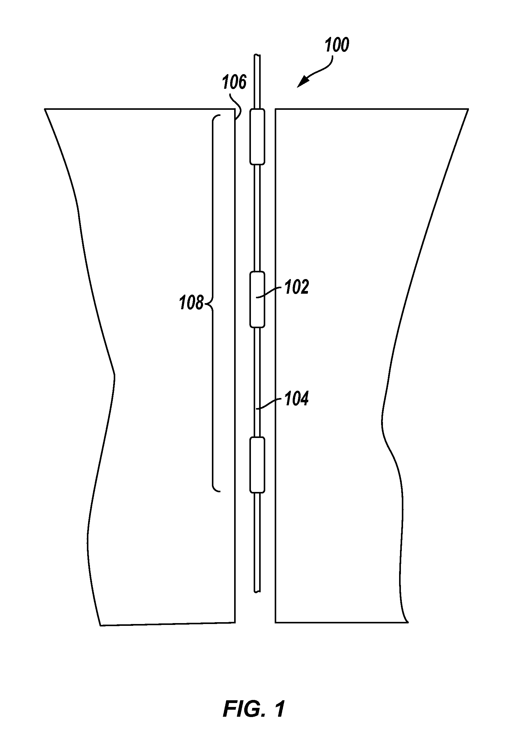
[0020]In the following detailed description, reference is made to the accompanying drawings that depict, by way of illustration, specific embodiments in which the disclosure may be practiced. However, other embodiments may be utilized, and structural, logical, and configurational changes may be made without departing from the scope of the disclosure. The illustrations presented herein are not meant to be actual views of any particular sensor, sensor array, assembly, or component thereof, but are merely idealized representations that are employed to describe embodiments of the present disclosure. The drawings presented herein are not necessarily drawn to scale. Additionally, elements common between drawings may retain the same numerical designation.

[0021]Although some embodiments of sensors of the present disclosure are depicted as being used and employed as pressure sensors utilizing one or more quartz resonator sensors, persons of ordinary skill in the art will understand that the ...


PUM


Abstract

Downhole distributed pressure sensor arrays include sensor housings each comprising at least one pressure sensor in a pressure housing. Downhole pressure sensors include a housing, at least one pressure sensor in a pressure housing portion of the housing, and at least one isolation element positioned at an outer wall of the housing.

Description

CROSS-REFERENCE TO RELATED APPLICATION[0001]This application claims the benefit of U.S. Provisional Patent Application Ser. No. 62 / 074,510, filed Nov. 3, 2014, the disclosure of which is hereby incorporated herein in its entirety by this reference.TECHNICAL FIELD[0002]Embodiments of the present disclosure relate to sensors for measurement of one or more of pressure and temperature in a subterranean wellbore and, more particularly, to distributed arrays of such sensors, pressure sensors, related assemblies, and associated methods.BACKGROUND[0003]In some applications, e.g., oil and gas production, it may be desirable to collect data from along a particular interval (e.g., length, depth) of a wellbore to obtain information regarding pressure and / or temperature gradients within the wellbore by employing a number of sensors to measure pressure and / or temperature sensors distributed in an array extending substantially along the wellbore interval. When implemented in a downhole environment...

Claims


Application Information

Patent Timeline
Patent Type & Authority Applications(United States)
IPC IPC(8): E21B47/01E21B47/06
CPCE21B47/06E21B47/011E21B47/017E21B47/01H03H9/19G01L11/04G01L9/085
Inventor LEEFLANG, BRIAN T.BROWN, G. SCOTT
Owner QUARTZDYNE
Learn More