
Expandable interbody implant

a technology of expandable implants and interbody parts, which is applied in the field of expandable interbody implants, can solve the problems of unreliable maintenance of related art implants, unoptimized oblique placement, and difficulty in maintaining related art implants, so as to prevent the formation of pockets, prevent the loss and maintain the volume of bone graft material substantially constant

Active Publication Date: 2016-05-05
WARSAW ORTHOPEDIC INC
View PDF4 Cites 96 Cited by
  • Summary
  • Abstract
  • Description
  • Claims
  • Application Information

AI Technical Summary

Benefits of technology

The present invention provides an expandable interbody implant with improved driving link, allowing smooth and reliable expansion to a selected height. Additionally, it maintains a near-constant graft volume chamber to avoid formation of pockets in the bone graft as the implant expands. It also provides better control over loss of bone graft material stored within the implant during expansion. The implant has a bone graft storage portion that prevents lost of bone graft material and keeps the volume of the bone graft material substantially constant. Overall, the invention ensures a better and reliable expanded interbody implant that improves spinal surgery procedures.

Problems solved by technology

Oblique placement has not been optimized with the related art implants.
The related art implants, moreover, typically employ ramp-on-ramp linkage mechanisms, which have proven to be unreliable in enabling such implants to smoothly and reliably increase to a selected height desired by the surgeon.
In addition, the related art implants have experienced difficulty with maintaining, during insertion and expansion within the disc space, a selected volume of bone graft material stored in the implant.

Method used


Image

  • Expandable interbody implant
  • Expandable interbody implant
  • Expandable interbody implant

Examples


Embodiment Construction

[0033]Other embodiments of the invention will be apparent to those skilled in the art from consideration of the specification and practice of the invention disclosed herein. It is intended that the embodiments described below be considered as exemplary only, with a true scope and spirit of the invention being indicated by the appended claims.

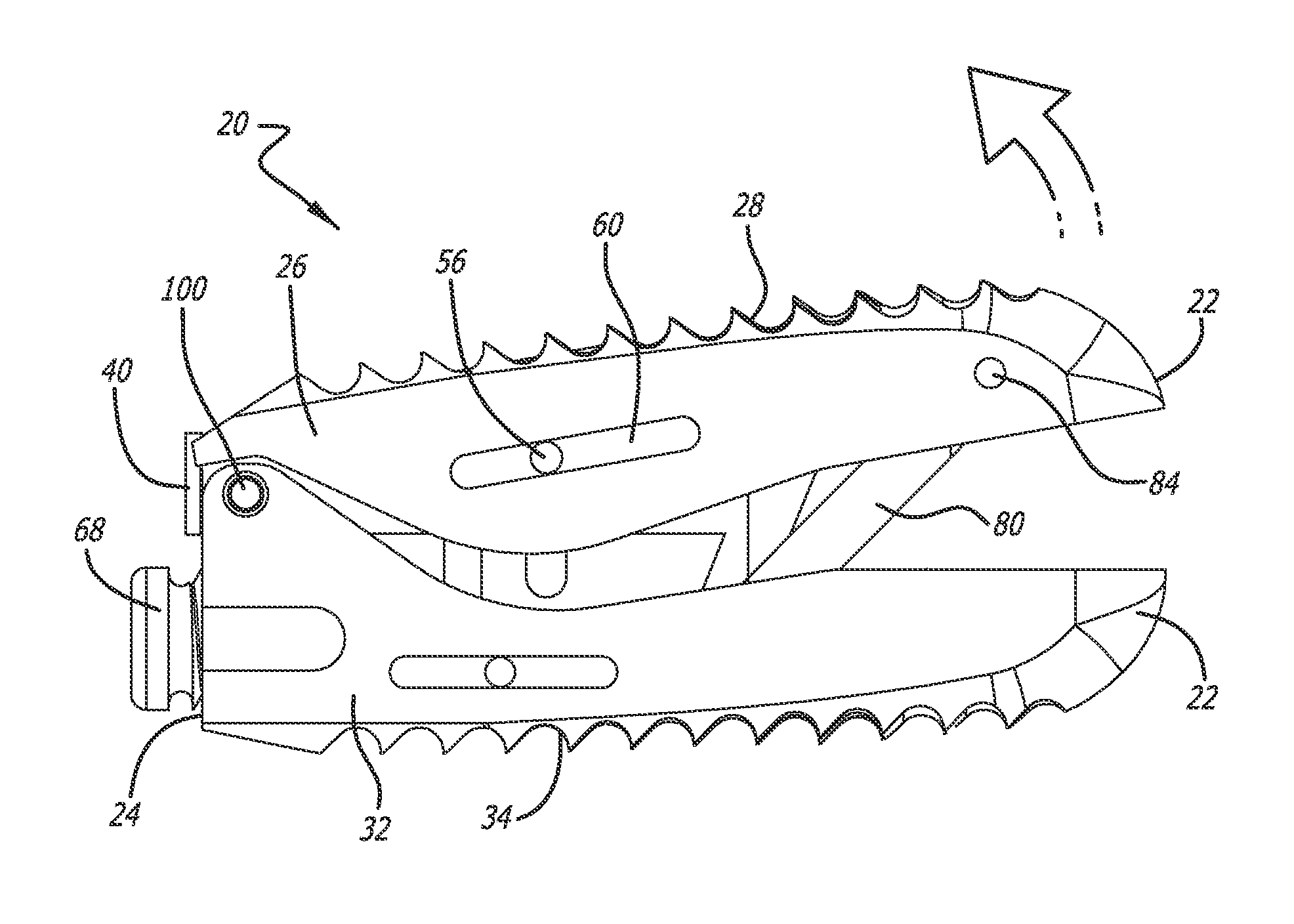
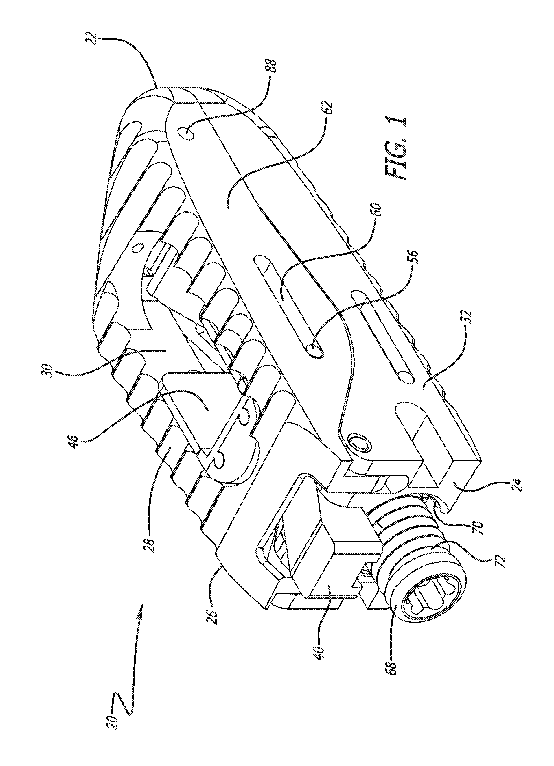
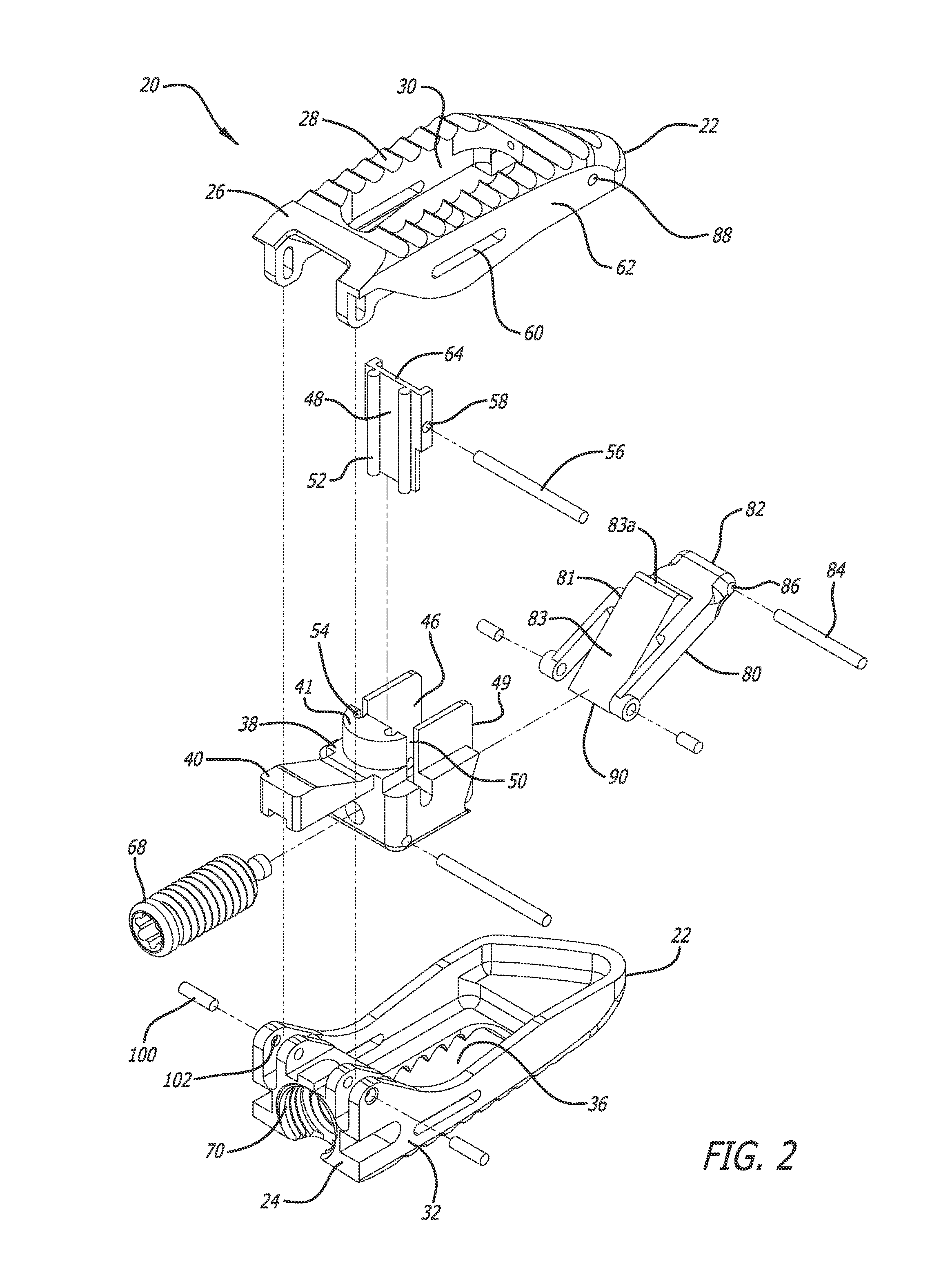
[0034]As shown in FIGS. 1-7, an expandable interbody implant 20 includes a leading end 22 and a trailing end 24. Implant 20 is adapted for insertion at least into a disc space having a surgically-corrected height between two adjacent vertebrae of a spine. Implant 20, moreover, is adapted for movement from an unexpanded position to an expanded position.

[0035]Implant 20 includes an upper member 26, having an upper surface 28 extending between leading end 22 and trailing end 24, with an upper opening 30 defined in upper surface 28.

[0036]Implant 20 further includes a lower member 32, having a lower surface 34 extending between leading end 22 and tra...


PUM


Abstract

An expandable interbody implant adapted for insertion at least into a disc space, between two adjacent vertebrae of a spine. An upper member and a lower member are pivotally connected at least by a drive link. A bone graft storage portion packed with a selected volume of bone growth material. A translational wall is provided between the bone graft storage portion and a trailing end of the implant. An actuator engages the bone graft storage portion, pushing it forward into engagement with the drive link, which pivots upward, moving the upper member upward away from the lower member. Upward movement of the upper member raises the translational wall to a position to assist in retention of the selected volume bone graft material within the hollow portion of the bone graft storage portion. Upward rotation of the drive link brings a face thereof into contact with a front of the bone graft storage portion, thereby retaining near constant volume of the bone graft material.

Description

BACKGROUND OF THE INVENTION[0001]The present invention relates generally to an expandable interbody implant, and more particularly to a lordotic expandable interbody implant adapted for oblique posterior, oblique anterior, co-axial posterior, or co-axial anterior, insertion and placement in a disc space having a surgically-corrected height between adjacent vertebral bodies in the lumbar spine.DESCRIPTION OF THE RELATED ART[0002]Lordotic expandable spinal fusion implants are known in the art. The lordotic, tapered configuration of such known implants assists in the restoration or enhancement of spinal lordosis in the lumbar spine. The expandability of such implants allows placement of a potentially larger implant through a smaller opening in a patient's body, with selective expansion in a selected direction providing the advantage of increasing the height of the implant and corresponding distraction of the disc space, without a concomitant increase in the width of the implant. The re...

Claims


Application Information

Patent Timeline
Patent Type & Authority Applications(United States)
IPC IPC(8): A61F2/44
CPCA61F2/4455A61F2002/4475A61F2002/30579A61F2002/30471A61F2002/30428A61F2002/3006A61F2002/30507A61F2002/30538A61F2002/30904A61F2002/30593A61F2002/30581A61B17/7071A61B17/7097A61F2/4611A61F2/447
Inventor MELKENT, ANTHONY J.ARMSTRONG, WILLIAM D.PALMATIER, STANLEY T.
Owner WARSAW ORTHOPEDIC INC
Learn More