
Flexible ethernet and multi link gearbox mapping procedure to optical transport network

a technology of optical transport network and multi-link gearbox, which is applied in the field of flexible ethernet mapping and multi-link gearbox (mlg) procedure with optical transport network, can solve the problems of significant cost/logic associated with the implementation

Active Publication Date: 2016-04-28
CIENA
View PDF10 Cites 53 Cited by
  • Summary
  • Abstract
  • Description
  • Claims
  • Application Information

AI Technical Summary

Benefits of technology

The patent describes a method for mapping a Physical Coding Sublayer (PCS) from Flexible Ethernet and / or Multi Link Gearbox (MLG) to Optical Transport Network (OTN). This method involves receiving one or more Virtual Lanes and mapping them into an associated Tributary Slot, which is then used to create an Optical Channel Data Unit flex (ODUflex). The number of Tributary Slots in OTN is determined based on the number of Virtual Lanes. The method can be performed using Remote Management (RM) channels or specific Alignment Markers (AM) to communicate the status of the Virtual Lanes. The Tributary Slots can be in an Optical Channel Payload Unit flex (OPUflex) that is mapped into an ODUflex. The virtual lanes can be about 5 Gb / s or greater, and a Payload Type (PT) can be defined in OTN designating a Tributary Slot of about 5 Gb / s or greater. The flexible de-mapping method can further include providing each virtual lane to a router. The technical effect of this patent is to provide a flexible and efficient method for mapping PCS from Flexible Ethernet and MLG to OTN.

Problems solved by technology

Long-Haul Dense Wave Division Multiplexing (DWDM) transport is expected to be the dominant cost and limiting contributor of an end-to-end link for many years to come.
This is a Media Access Control (MAC) / packet layer type of mapping in transport gear and has significant cost / logic associated with the implementation.

Method used


Image

  • Flexible ethernet and multi link gearbox mapping procedure to optical transport network
  • Flexible ethernet and multi link gearbox mapping procedure to optical transport network
  • Flexible ethernet and multi link gearbox mapping procedure to optical transport network

Examples


Embodiment Construction

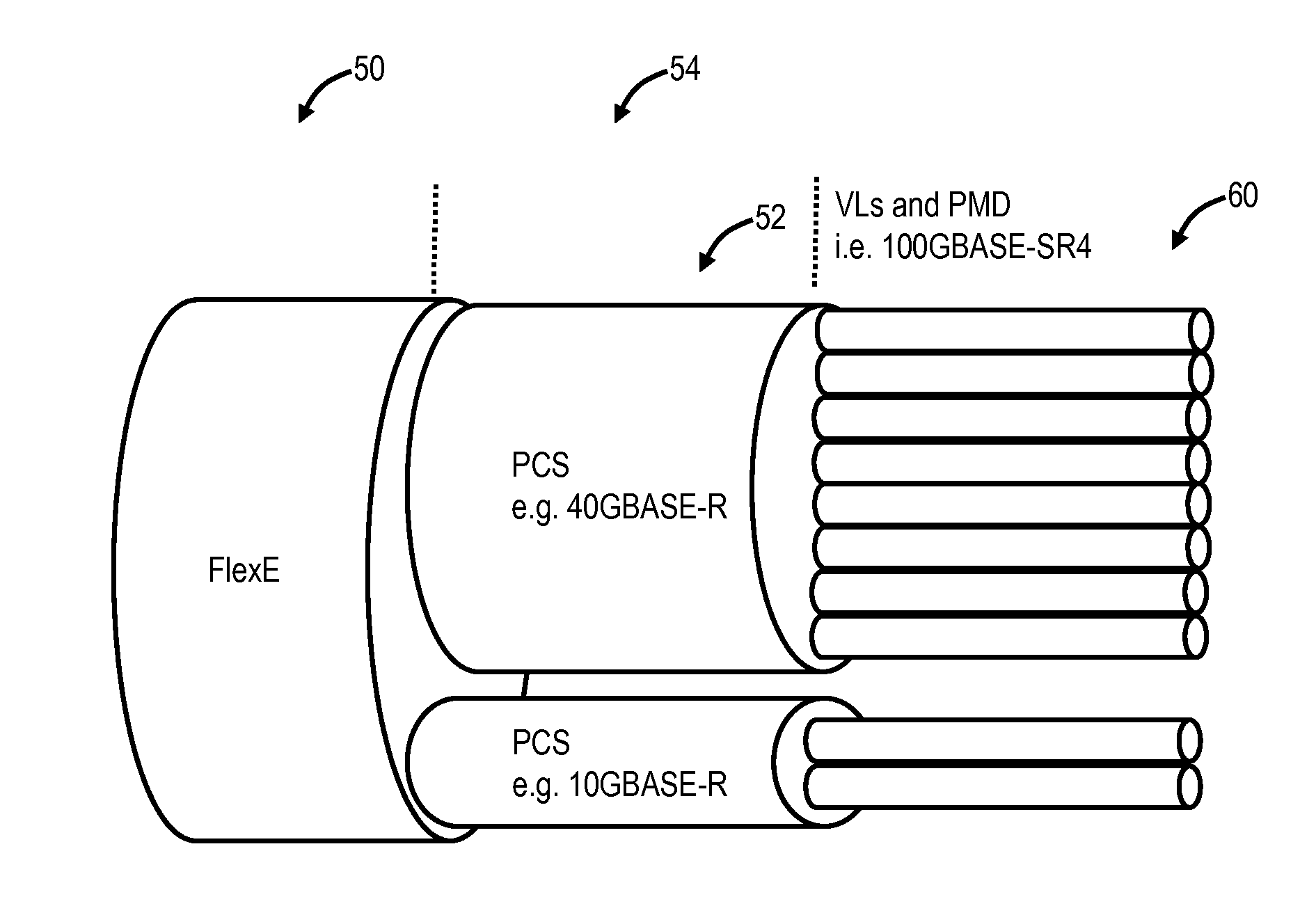
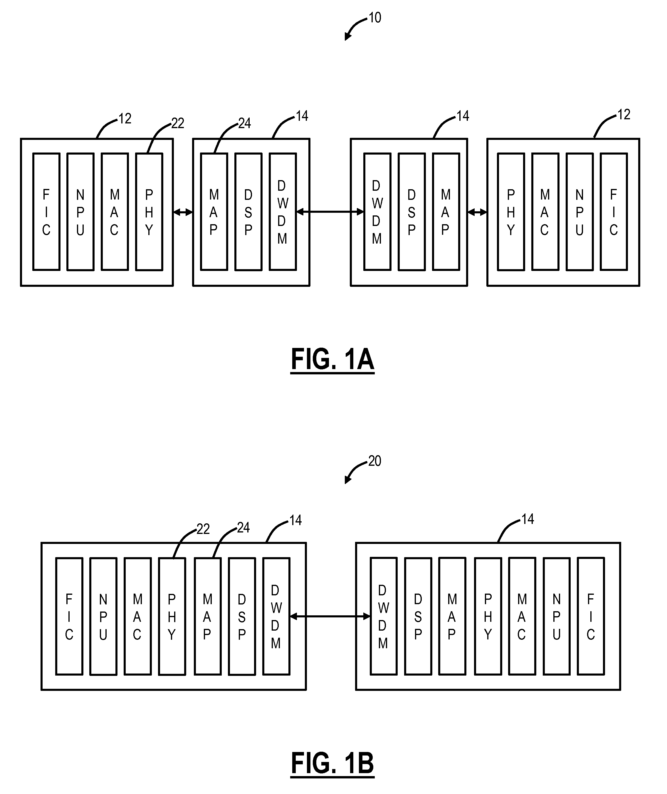
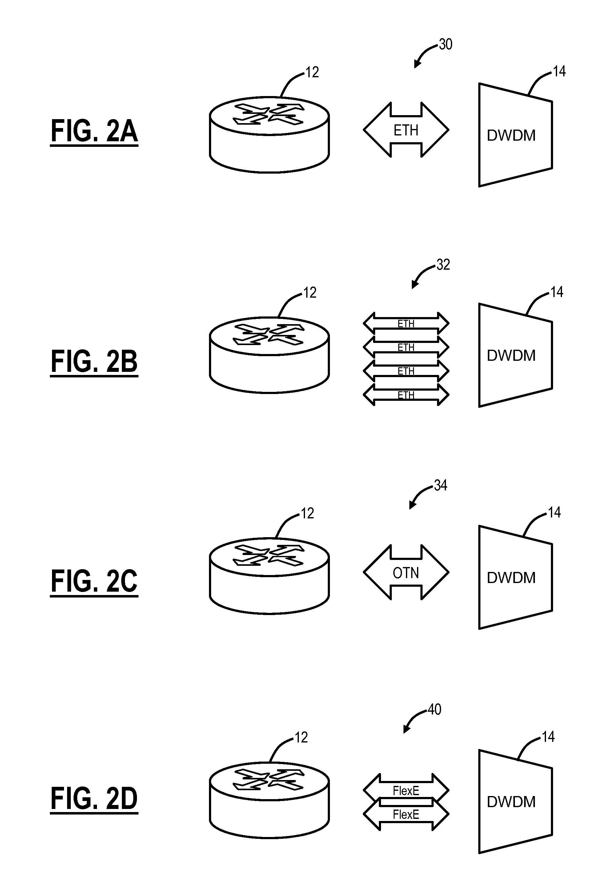
[0023]In various exemplary embodiments, a flexible Ethernet mapping process into OTN is described, which may be referred to as an ODUflex(MLG) (Multi Link Gearbox) or ODUflex(FlexE) mapping procedure, to support mapping into right-sized ODUflex connections. The flexible Ethernet mapping process maps the generalized MLG-style group of lanes (virtual PHYs / PMDs) into an OPUflex Tributary Slot (TS) structure, keeping PCS structures intact, and creates a single ODUflex container with a matching rate of FlexE for end-to-end flow. The ODUflex signal can be switched and multiplexed in OTN transport equipment and the like. Advantageously, the flexible Ethernet mapping process does not require alignment, reorder and deskewing of PCS lanes. This provides an efficient mechanism for equipment vendors and network operators to address the complexities with mapping FlexE shim PCS into flexible OTN containers. The flexible Ethernet mapping process can be implemented on client cards or the like, and ...


PUM


Abstract

A flexible mapping method to map a Physical Coding Sublayer (PCS) structure from Flexible Ethernet and / or Multi Link Gearbox (MLG) to Optical Transport Network (OTN), includes receiving one or more Virtual Lanes; and mapping each of the one or more Virtual Lanes into a Tributary Slot, wherein a rate and number of the Tributary Slot(s) in OTN is set based on a rate and number of the one or more Virtual Lanes. A transport system and a flexible de-mapping method are also described. The systems and methods map the generalized MLG-style group of lanes (virtual PHYs / PMDs) into an OPUflex Tributary Slot (TS) structure, keeping PCS structures intact, and creates a single ODUflex container with a matching rate of FlexE for end-to-end flow.

Description

CROSS-REFERENCE TO RELATED APPLICATIONS[0001]The present patent / patent application claims priority to U.S. Provisional Patent No. 62 / 068,315 filed on Oct. 24, 2014 entitled “FLEXIBLE ETHERNET AND MULTI LINK GEARBOX MAPPING PROCEDURE WITH OPTICAL TRANSPORT NETWORK,” the contents of which are incorporated by reference herein.FIELD OF THE DISCLOSURE[0002]The present disclosure relates generally to networking systems and methods. More particularly, the present disclosure relates to a flexible Ethernet mapping and Multi Link Gearbox (MLG) procedure with Optical Transport Network (OTN).BACKGROUND OF THE DISCLOSURE[0003]Long-Haul Dense Wave Division Multiplexing (DWDM) transport is expected to be the dominant cost and limiting contributor of an end-to-end link for many years to come. There is momentum in the industry to define a flexible end-to-end packet flow with a flexible Ethernet architecture to adapt to line capabilities. A consortium of companies is defining a Physical Coding Sublay...

Claims


Application Information

Patent Timeline
IPC IPC(8): H04J14/02H04B10/27
CPCH04B10/27H04J14/0227H04L12/6418H04J3/1652H04J3/1658H04J2203/0085
Inventor GAREAU, SEBASTIENMANILOFF, ERIC
Owner CIENA
Learn More