Coronary sinus medical electrical lead

Inactive Publication Date: 2016-04-28
MEDTRONIC INC
View PDF1 Cites 0 Cited by
  • Summary
  • Abstract
  • Description
  • Claims
  • Application Information

AI Technical Summary

Benefits of technology

The patent describes a medical electrical lead with electrodes that are aligned along a first longitudinal plane, while the opposed second longitudinal plane lacks electrically active electrodes or they are insulated. This design operates like an automobile with a masked side, similar to a passenger side, and an active side, like a driver side, where the electrodes direct the electrical current towards the myocardium without simply blasting electrical stimuli in all directions. This reduces the amount of energy needed and avoids phrenic nerve stimulation. The lead also results in lower pacing thresholds, meaning less energy is needed, and higher pacing impedance, reducing the current drain on the implantable medical device. This may increase the life of the device.

Problems solved by technology

Additionally, the lead results in higher pacing impedance due to use of electrodes with a decreased surface area.
Decreased current drain and energy consumption may increase the life of the implantable medical device.

Method used


Image

  • Coronary sinus medical electrical lead
  • Coronary sinus medical electrical lead
  • Coronary sinus medical electrical lead

Examples


Embodiment Construction

[0034]The following detailed description is exemplary in nature and is not intended to limit the scope, applicability, or configuration of the disclosure in any way. Rather, the following description provides practical illustrations for implementing exemplary embodiments of the present invention. Constructions, materials, dimensions, and manufacturing processes suitable for making embodiments of the present are known to those of skill in the field of the invention.

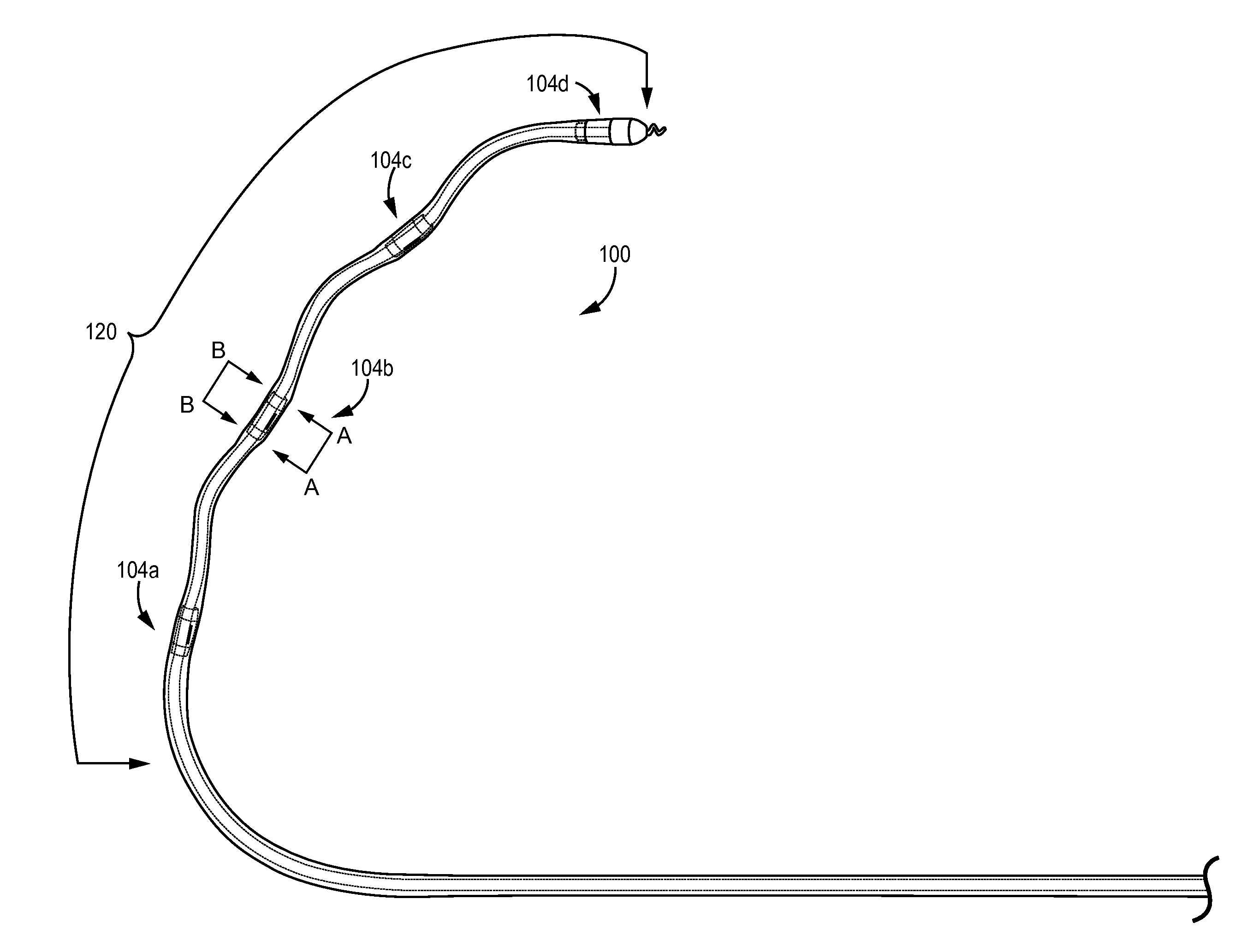
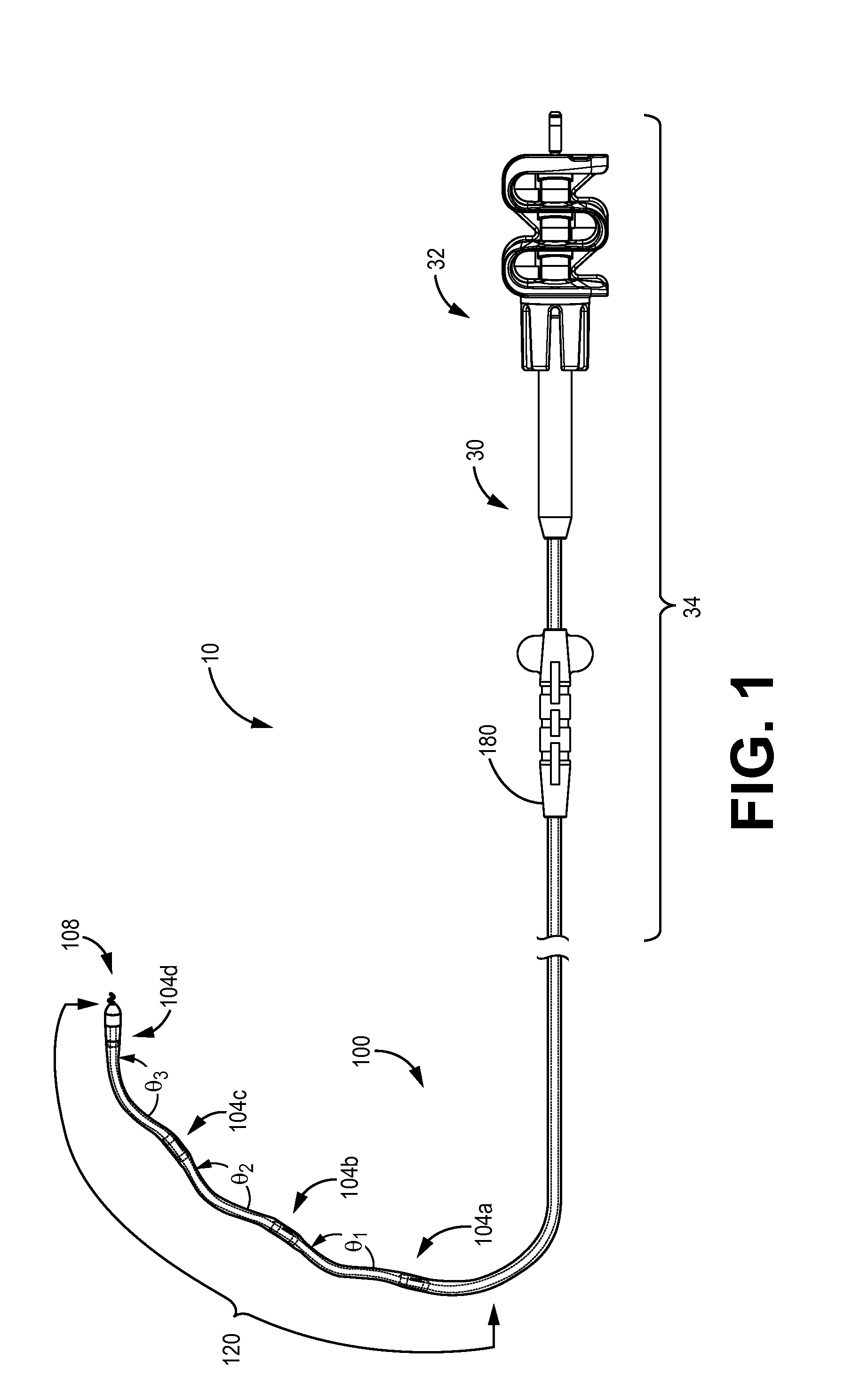
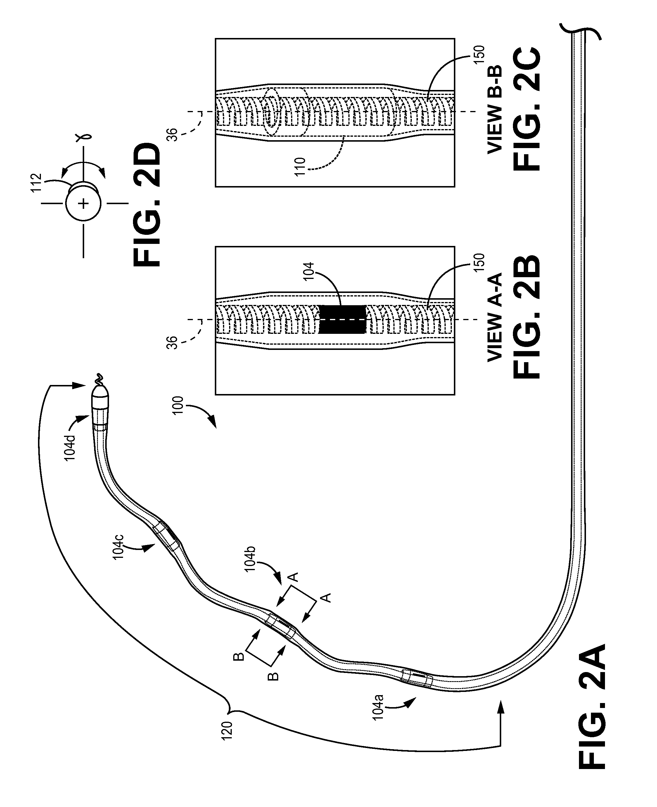
[0035]FIGS. 1-2 is a plan view of an exemplary intravenous medical electrical lead 10 connected through to a guide catheter 34 such as the ATTAIN CATHETER® developed and sold by Medtronic, Inc. of Minneapolis, Minn. Lead 10 is configured to deliver electrical stimulation to tissue (e.g. ventricular cardiac pacing) and / or sense signals from the tissue. Lead 10 includes proximal end and a distal end 120 with a lead body 150 therebetween that generally defines a longitudinal axis. At the proximal end is located an in-line bip...


PUM


Abstract

The present invention may comprise an improvement to the prior art leads as disclosed above. In a preferred embodiment, the invention comprises an medical electrical lead that includes an elongated lead body. The elongated lead body comprises a length between a proximal end and a curved distal end, the lead body defining a longitudinal axis extending between the proximal end and the distal end. The lead body having an outer circumference and provided with a set of electrodes circumferentially spaced apart. Each electrode includes an electrically active portion and an insulated portion at an outer circumference of the electrode along a first longitudinal plane and along a second longitudinal plane diametrically opposed to the first longitudinal plane are insulated electrodes. Each electrode is configured to include a guide aid to engage with a non-conductive housing.

Description

TECHNICAL FIELD[0001]The present disclosure pertains to medical electrical leads, and, more particularly, to implantable medical electrical leads that reduce undesired neural stimulation.BACKGROUND[0002]Implantable medical devices, for example cardiac pacemakers and defibrillators, often include elongate medical electrical leads having one or more electrodes to sense electrical activity and deliver therapeutic stimulation. With the advent of left ventricular pacing to alleviate heart failure, leads have been advanced into the coronary veins in order to position the electrodes of the leads at left ventricular pacing sites, typically located in proximity to the base of the left ventricle. Although a variety of left ventricular pacing leads, along with methods for implanting such leads, have been developed, there is still a need for a lead including features that facilitate delivery to, and fixation at, sites in the coronary vasculature.[0003]Numerous types of medical electrical leads ...

Claims


Application Information

Patent Timeline
IPC IPC(8): A61N1/05
CPCA61N2001/0585A61N1/0565
Inventor SOMMER, JOHN L.CLEMENS, WILLIAM J.FRANKE, LINDA L.
Owner MEDTRONIC INC
Why Eureka
Try Eureka