Device and method for x-ray phase contrast imaging

a technology of phase contrast imaging and device, which is applied in the field of device and a method for slot scanning xray phase contrast imaging, can solve the problem of complicated options

Active Publication Date: 2016-04-28
SIEMENS HEATHCARE GMBH
View PDF5 Cites 7 Cited by
  • Summary
  • Abstract
  • Description
  • Claims
  • Application Information

AI Technical Summary

Benefits of technology

The disclosed embodiments allow for a device to be made without the need for expensive and exact mechanical adjustments of components.

Problems solved by technology

Therefore, this option is more complicated.

Method used


Image

  • Device and method for x-ray phase contrast imaging
  • Device and method for x-ray phase contrast imaging
  • Device and method for x-ray phase contrast imaging

Examples


Embodiment Construction

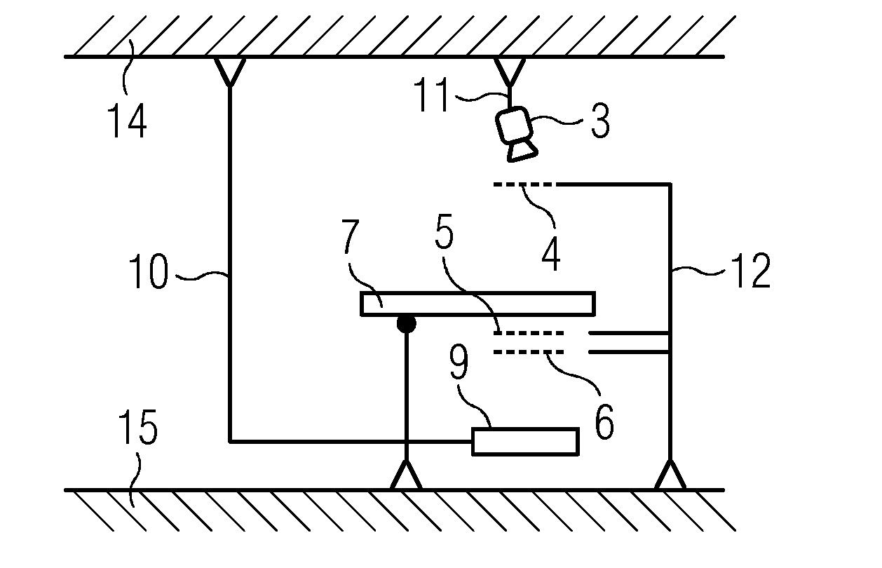
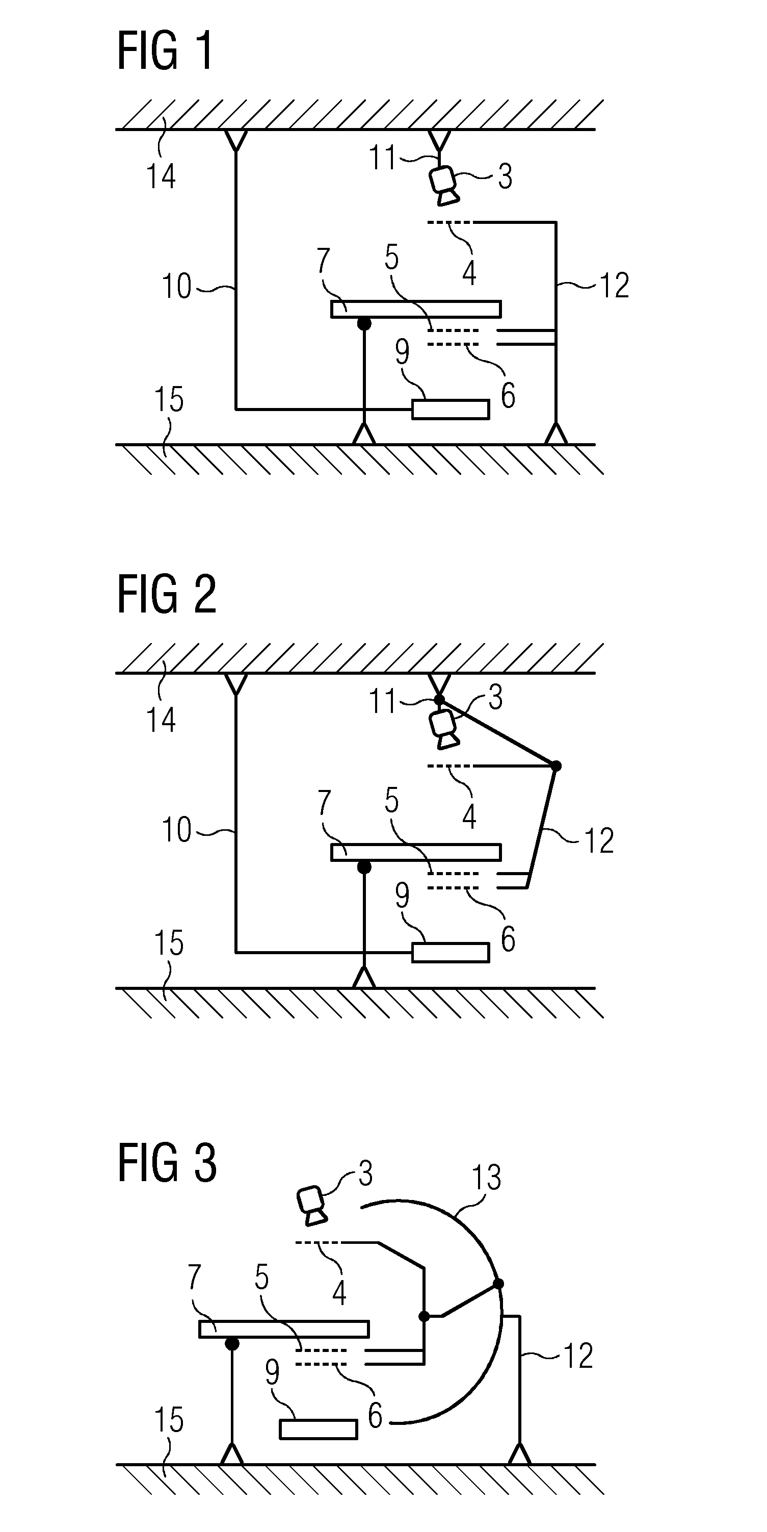
[0035]FIGS. 1-3 depict schematic examples of slot scanning devices for x-ray phase contrast imaging, including an x-ray emitter 3, an x-ray detector 9, a patient couch 7 and a grating arrangement. The grating arrangement has a first x-ray grating 4, a second x-ray grating 5, and a third x-ray grating 6. The second and third x-ray gratings 5 and 6 are situated under the couch board (e.g., tabletop) of the patient couch 7 in front of the x-ray detector 9. The patient couch 7 serves to mount an object (not depicted) that is irradiated by the x-ray beam fan of the x-ray emitter 3. The object (e.g., a patient) is displaceable together with the patient couch 7.

[0036]In FIGS. 1 and 2, the x-ray detector 9 is fastened to a first ceiling stand 10 and may be displaced with the aid of the first ceiling stand 10 arranged at the ceiling 14. In FIG. 1, the x-ray emitter 3 is connected to a second ceiling stand 11 and may be displaced therewith. The second ceiling stand 11 is arranged at the ceili...


PUM


Abstract

A device for slot scanning phase contrast x-ray imaging, includes an x-ray emitter, a plurality of x-ray gratings, a patient couch, and an x-ray detector. Position marker elements are arranged and configured in the beam path of the x-ray emitter such that the position marker elements are visible in an x-ray image. In the x-ray image, a relative position of an object on the patient couch in relation to an x-ray beam fan of the x-ray emitter may be established from a location and a distance of the position marker elements from one another.

Description

CROSS-REFERENCE TO RELATED APPLICATIONS[0001]The present patent document claims the benefit of DE 102014221599.4, filed on Oct. 23, 2014, which is hereby incorporated by reference in its entirety.TECHNICAL FIELD[0002]The present embodiments relate to a device and a method for slot scanning x-ray phase contrast imaging.BACKGROUND[0003]X-ray phase contrast imaging is an x-ray imaging method that, unlike conventional x-ray instruments, does not only use the absorption by an object as source of information. X-ray phase contrast imaging combines the absorption with the shift of the phase of the x-ray radiation when passing through the object. The information content is disproportionately higher because the absorption supplies accurate images of the strongly absorbing bones and the phase contrast makes sharp images of the structures of the soft tissue. This offers the possibility of being able to identify pathological changes, such as the emergence of tumors, vessel constrictions, or path...

Claims


Application Information

Patent Timeline
IPC IPC(8): A61B6/00A61B6/04
CPCA61B6/484A61B6/4291A61B6/4035A61B6/0492A61B6/0407A61B6/5235
Inventor FREUDENBERGER, JORG
Owner SIEMENS HEATHCARE GMBH
Why Eureka
Try Eureka