Brush Drying Support and Method of Using Same

a technology of brush head and support, which is applied in the direction of machine support, lighting and heating apparatus, mechanical apparatus, etc., can solve the problems of preventing the optimal draining of water downward off the bristles loosening the glue, and not being able to achieve optimal angle, so as to improve the accessibility of brushes, improve the cleanliness of the brush head, and preserve the effect of longevity

Inactive Publication Date: 2016-04-14
LEE DIANE
View PDF34 Cites 1 Cited by
  • Summary
  • Abstract
  • Description
  • Claims
  • Application Information

AI Technical Summary

Benefits of technology

[0010]The present invention relates to a new brush drying support and method for drying brushes, on the support. The invention comprises a support, comprised of a structure with a generally planar top portion, disposed at an optimal angle for retaining and draining brushes. This top portion is covered with a gripping material that holds brushes placed directly on the support, without requiring further retaining means. The proper method for retaining and draining a wet brush occurs when a brush is placed on an angled top portion of said support, with the brush stem located above the brush head. Further, the brush head overhangs the bottom edge of the top (angled) portion of the support. This novel brush support, and method of drying brushes, provide several advantages over the prior art; namely, improved cleanliness of the brush head, preservation and longevity of the brush head, support of multiple brushes in a small space, and improved user accessibility to brushes. Further, the invention provides compact brush storage without slots, holes or bulky retaining means.

Problems solved by technology

A problem with supporting brushes in the vertical position is that it is not the optimal angle to preserve the cleanliness, shape and quality of the brush.
This arrangement prevents water from optimally draining downward off the bristles of the brush head.
When water collects in the brush head, it can loosen the glue that attaches the bristles to the brush head, and compromise the quality of the brush.

Method used


Image

  • Brush Drying Support and Method of Using Same
  • Brush Drying Support and Method of Using Same
  • Brush Drying Support and Method of Using Same

Examples


Embodiment Construction

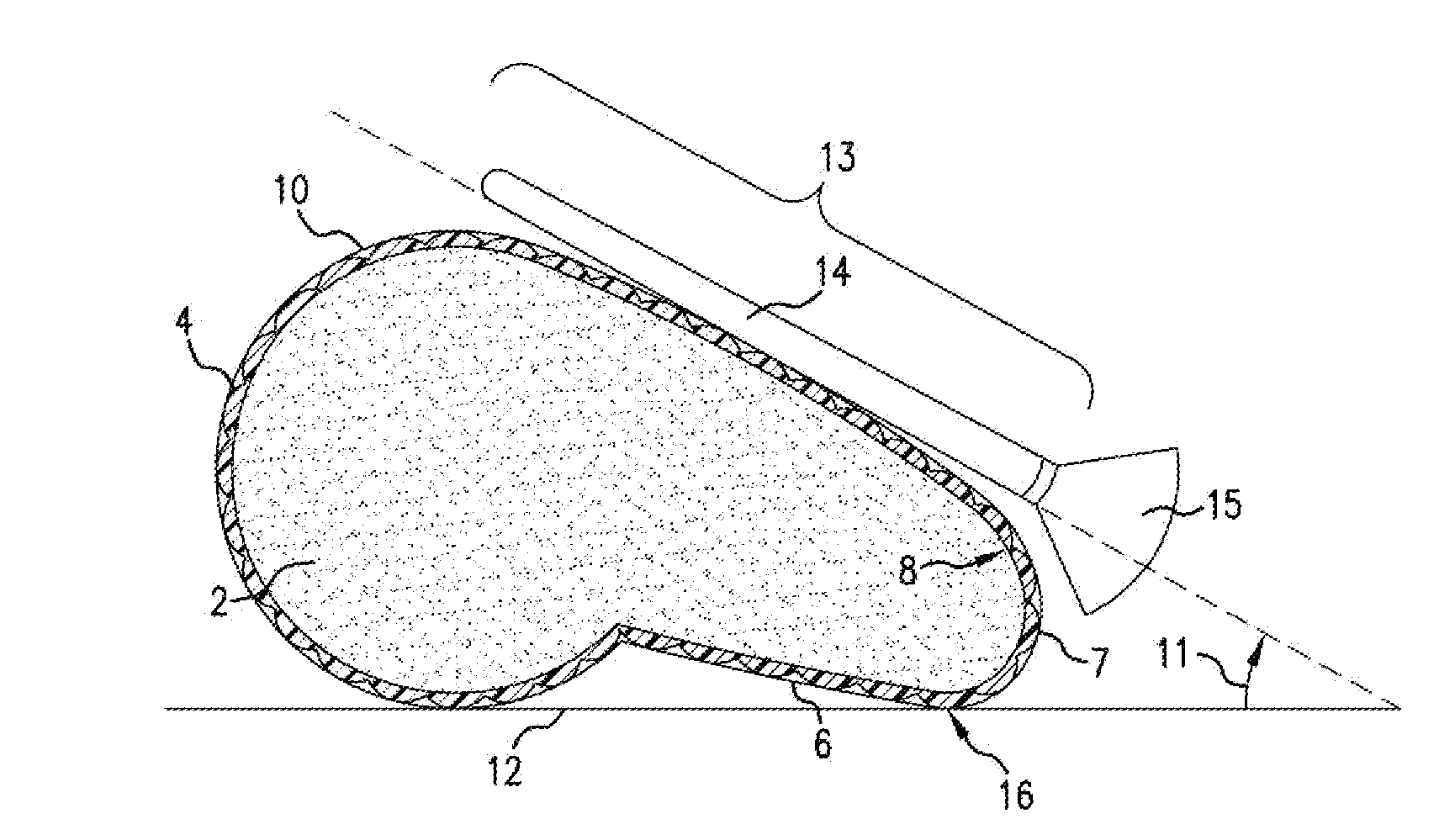
[0018]Referring now to the invention in more detail, see FIG. 1 to FIG. 4. These figures show a brush support 1 intended to support cosmetic brushes or similar types of brushes, including but not limited to artist and / or paint brushes, for drying and storage. It is intended that different embodiments of the invention may be used and structural changes may be made without departing from the scope and spirit of the invention. The following detailed description should not be limited to the embodiments shown, but rather, should be read broadly to enable similar embodiments. The scope of the present invention is defined by the claims.

[0019]Referring to FIG. 1 to FIG. 4, the brush support 1 is generally comprised of a structure 2, gripping material 3 and end pieces 10. Structure 2 is generally comprised of a generally planar top portion 5, a generally curved back portion 4, a generally planar bottom portion 6 and a generally curved front portion 7. As depicted in FIG. 1 to FIG. 4, general...


PUM


Abstract

The present invention relates to a new brush drying support and method for drying brushes, on the support. The invention comprises a support, comprised of a structure with a generally planar top portion, disposed at an optimal angle for retaining and draining brushes. This top portion is covered with a gripping material that holds brushes placed directly on the support, without requiring further retaining means. The proper method for retaining and draining a wet brush occurs when a brush is placed on an angled top portion of said support, with the brush stem located above the brush head. Further, the brush head overhangs the bottom edge of the top (angled) portion of the support. This novel brush support, and method of drying brushes, provide several advantages over the prior art; namely, improved cleanliness of the brush head, preservation and longevity of the brush head, support of multiple brushes in a small space, and improved user accessibility to brushes. Further, the invention provides compact brush storage without slots, holes or bulky retaining means.

Description

CROSS-REFERENCE TO RELATED APPLICATIONS[0001]Not ApplicableSTATEMENT REGARDING FEDERALLY SPONSORED RESEARCH OR DEVELOPMENT[0002]Not ApplicableREFERENCE TO SEQUENCE LISTING, A TABLE, OR A COMPUTER PROGRAM LISTING COMPACT DISK APPENDIX[0003]Not ApplicableBACKGROUND OF THE INVENTION[0004]The present invention is in the technical field of HOLDERS / SUPPORTS. More particularly, the present invention is in the technical field of BRUSH HOLDERS. More particularly, the present invention relates to BRUSH DRYING SUPPORTS.[0005]Historically, cosmetic and / or artistic brush holders have been designed to maintain brushes in a vertical position to allow for the brushes to dry over time. As an example, see U.S. Pat. No. 8.720,703, issued May 13, 2014, to Pressler (“the '703 Patent”), and U.S. Pat. No. 7,234,602, issued Jun. 26, 2007, to Roberti (“the '602 Patent”). A problem with supporting brushes in the vertical position is that it is not the optimal angle to preserve the cleanliness, shape and qual...

Claims


Application Information

Patent Timeline
Patent Type & Authority Applications(United States)
IPC IPC(8): A46B17/08F16M13/00F16B2/00
CPCA46B17/08F16M13/00F16B2/005A46B17/02
Inventor LEE, DIANE
Owner LEE DIANE
Why Eureka
Try Eureka