Headset amplification circuit with error voltage suppression

Active Publication Date: 2016-04-07
ANALOG DEVICES INT UNLTD
View PDF1 Cites 22 Cited by
  • Summary
  • Abstract
  • Description
  • Claims
  • Application Information

AI Technical Summary

Benefits of technology

The patent text describes a circuit for controlling the voltage in a headset driver. The circuit uses a switched capacitor to efficiently add the desired noise or error voltage to the bias voltage. This arrangement minimizes the impact on the bias voltage generator and reduces power consumption. The circuit also includes a large capacitance to prevent noticeable loading of the first capacitor. Overall, the circuit provides a more efficient and effective way to control the voltage in a headset driver.

Problems solved by technology

Since the ground connection in the 4-pin jack plug is shared between the left and right loudspeakers and the microphone, any resistance therein introduces an undesirable audio signal component, i.e. a noise or error signal, on the microphone ground wire.
Since the DC bias voltage for the microphone is fixed relative to the ground node or potential of the headset driver circuit, the noise or error signal represents distortion that may add an undesirable echo from the loudspeaker signal or signals to the output signal of the microphone preamplifier.
However, this solution is often impractical for example when using semiconductor switches to perform the ground switching.
In the latter situation, the larger dimensions required of the semiconductor switches lead to an increase of semiconductor die area and an accompanying increase of manufacturing costs of the semiconductor die.
This increase of manufacturing costs is unacceptable for numerous types of cost-sensitive consumer equipment and applications.

Method used


Image

  • Headset amplification circuit with error voltage suppression
  • Headset amplification circuit with error voltage suppression
  • Headset amplification circuit with error voltage suppression

Examples


Embodiment Construction

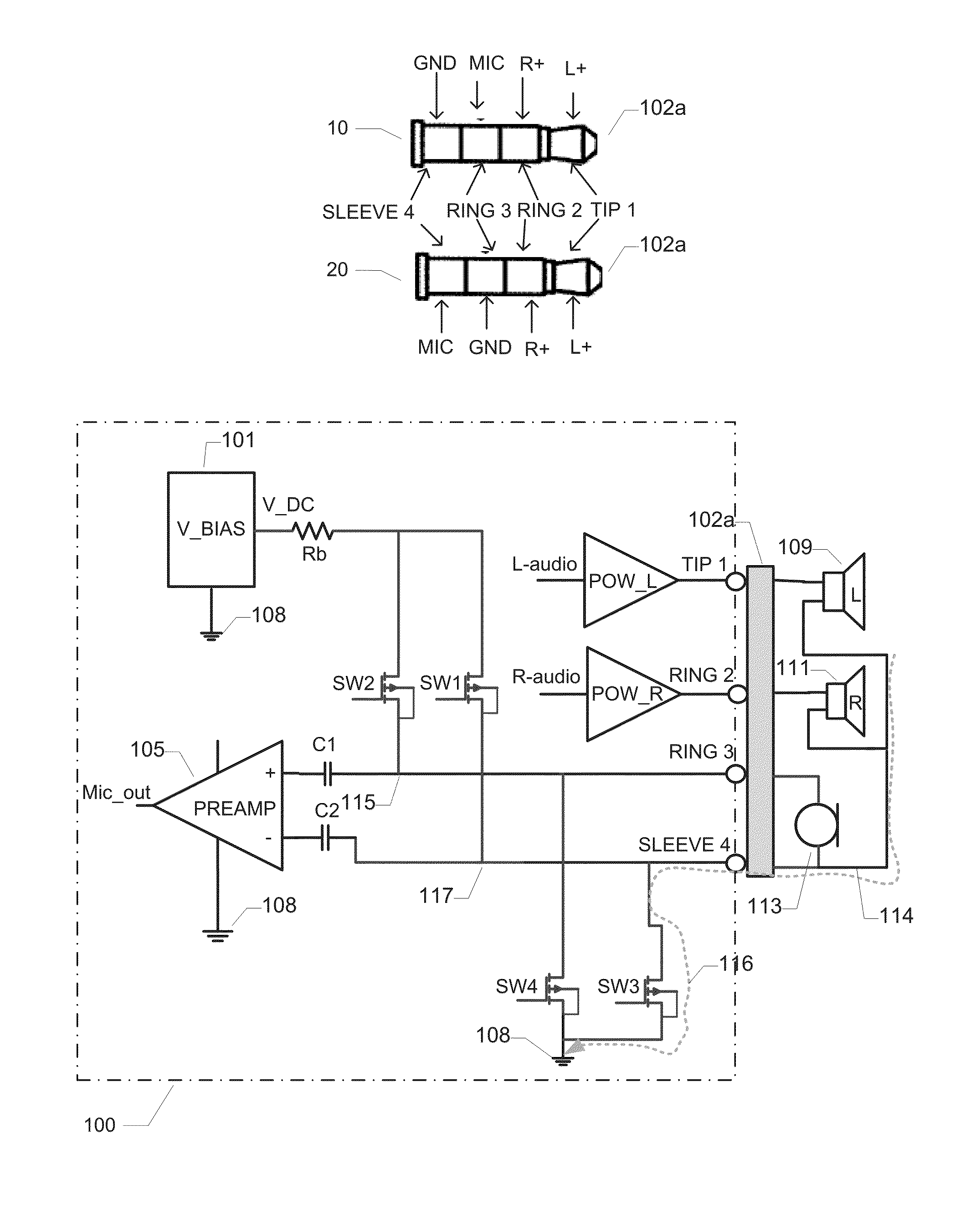
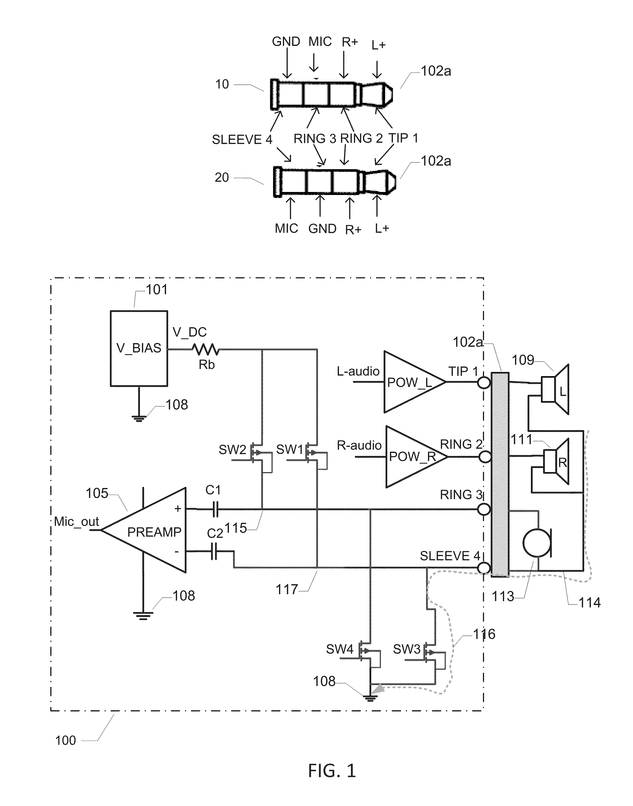
[0030]FIG. 1 is a schematic block diagram of a headset driver circuit 100 in accordance with a first embodiment of the invention. The headset driver circuit 100 may be part of an embedded audio amplification system of a portable communication device such as a smartphone, mobile phone, audio enable tablet etc. The portable communication device may for example be connected to an external mono or stereo headset or earphone using a 3-terminal or 4-terminal 2.5 mm or 3.5 mm jack plug on the headset. Various components of a stereo headset are schematically depicted on the drawing. The stereo headset comprises a left ear speaker 109 and a right ear speaker 111 and a microphone 113. The headset also comprises a common ground connection, wire or trace 114 which is shared between the microphone and the left and right ear speakers. This common ground connection 114 is connected to position or pin 4 of a four pin jack plug 102a. This pin 4 may be the Sleeve of the jack plug or it may be Ring 3 ...


PUM


Abstract

A headset driver circuit is described which comprises a connector interface. The connector interface comprises a first terminal, a second terminal and a third terminal for establishing respective electrical connections to a first speaker, a microphone and a common ground node of a headphone, earphone or headset, respectively. A first power amplifier is coupled to the first terminal to supply a first audio output signal to the first speaker of the headset. A first switch arrangement comprises a first ground switch is configured for selectively connecting and disconnecting the second terminal and a ground node of the headset driver circuit. The headset driver circuit further comprises a second ground switch configured for selectively connecting and disconnecting the third terminal and the ground node. The headset driver circuit also comprises a differential preamplifier, e.g. a microphone preamplifier, configured to generate a microphone output voltage where the differential preamplifier comprises a first signal input coupled to the second terminal and a second signal input coupled to the third terminal of the connector interface. An error suppression circuit is configured to sense or sample a noise or error voltage at the second terminal when ground connected or the third terminal when ground connected. The error suppression circuit is further configured to add the sensed or sampled noise or error voltage to a predetermined DC bias voltage and generate an error compensated DC bias voltage for the ungrounded one of the second and third terminals of the connector interface.

Description

FIELD OF THE INVENTION[0001]The present invention relates to a headset driver circuit which comprises a connector interface. The connector interface comprises a first terminal, a second terminal and a third terminal for establishing respective electrical connections to a first speaker, a microphone and a common ground node of a headset, headphone or earphone, respectively. A first power amplifier is coupled to the first terminal to supply a first audio output signal to the first speaker of the headset. A first switch arrangement comprises a first ground switch is configured for selectively connecting and disconnecting the second terminal and a ground node of the headset driver circuit. The headset driver circuit further comprises a second ground switch configured for selectively connecting and disconnecting the third terminal and the ground node. The headset driver circuit also comprises a differential preamplifier, e.g. a microphone preamplifier, configured to generate a microphone...

Claims


Application Information

Patent Timeline
IPC IPC(8): H04R1/10H03F3/181
CPCH03F3/181H04R1/1041H03F3/187H03F3/45475H03F2200/03H03F2200/189H03F2203/45541H03F2203/45544H03F2203/45586H03F2203/45588H03F2203/45622H04R5/033H04R5/04H04R29/001
Inventor WISMAR, ULRIK SORENSENKIM, SEJUN
Owner ANALOG DEVICES INT UNLTD
Why Eureka
Try Eureka