Thin film fabricating apparatus and manufacturing method of organic light emitting device using the same

a manufacturing method and thin film technology, applied in the direction of electrolysis organic material coating, gasless spraying, coating, etc., can solve the problems of reducing the efficiency of manufacturing a large substrate, and affecting the efficiency of production

Active Publication Date: 2016-04-07
SAMSUNG ELECTRONICS CO LTD
View PDF6 Cites 17 Cited by
  • Summary
  • Abstract
  • Description
  • Claims
  • Application Information

AI Technical Summary

Benefits of technology

The technical effect of this patent is that it describes how traditional methods of supplying materials through a small hole can't always produce consistent layers at a nanometer scale when trying to manufacture products on a large scale.

Problems solved by technology

The patent text discusses the methods of fabricating an organic electroluminescent device, which can be used for thin displays and lighting. The technical problem addressed is the limitations of current methods, such as high manufacturing costs and difficulties in achieving high efficiency and long life-span in a stacked structure using materials with different characteristics. The text also mentions the use of an electro-spray method for fabricating the device, but this method has limitations such as long treatment time and potential for electrolytic corrosion and pollution.

Method used


Image

  • Thin film fabricating apparatus and manufacturing method of organic light emitting device using the same
  • Thin film fabricating apparatus and manufacturing method of organic light emitting device using the same
  • Thin film fabricating apparatus and manufacturing method of organic light emitting device using the same

Examples


Embodiment Construction

[0039]The embodiments now will be described more fully hereinafter with reference to the accompanying drawings, in which various embodiments are shown. These embodiments may, however, be embodied in many different forms, and should not be construed as limited to the embodiments set forth herein. Rather, these embodiments are provided so that this disclosure will be thorough and complete, and will fully convey the scope of the invention to those skilled in the art. Like reference numerals refer to like elements throughout.

[0040]It will be understood that when an element is referred to as being “on” another element, it can be directly on the other element or intervening elements may be present therebetween. In contrast, when an element is referred to as being “directly on” another element, there are no intervening elements present.

[0041]It will be understood that, although the terms “first,”“second,”“third” etc. may be used herein to describe various elements, components, regions, lay...


PUM


Abstract

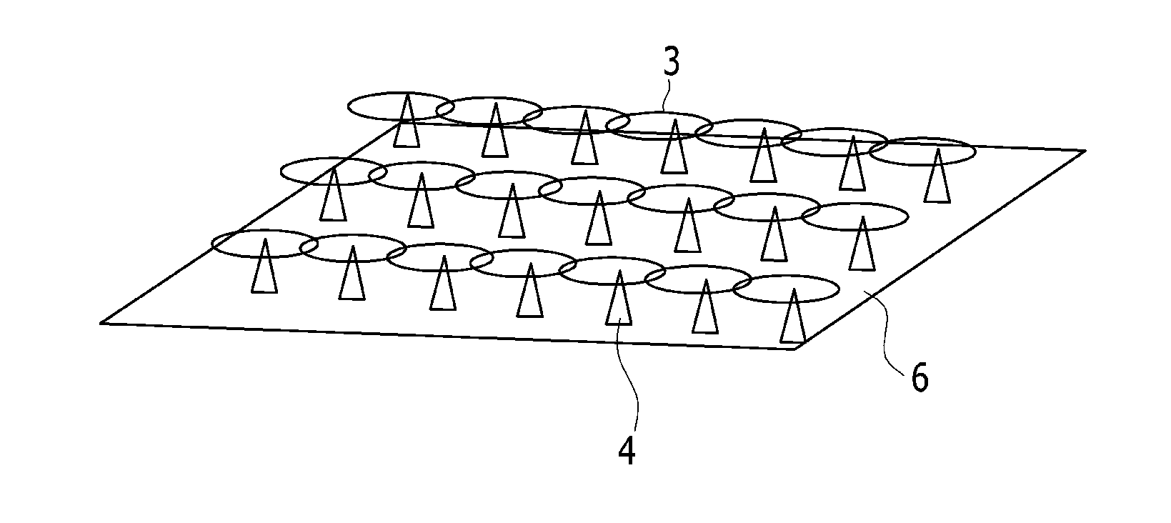
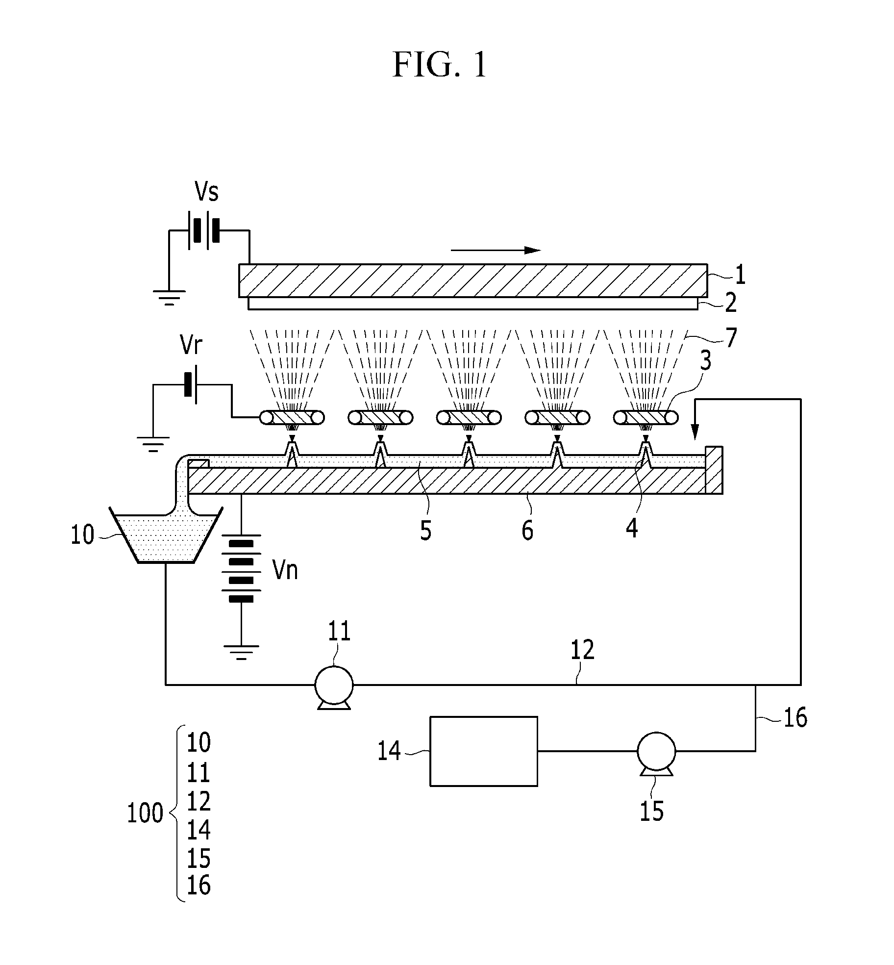
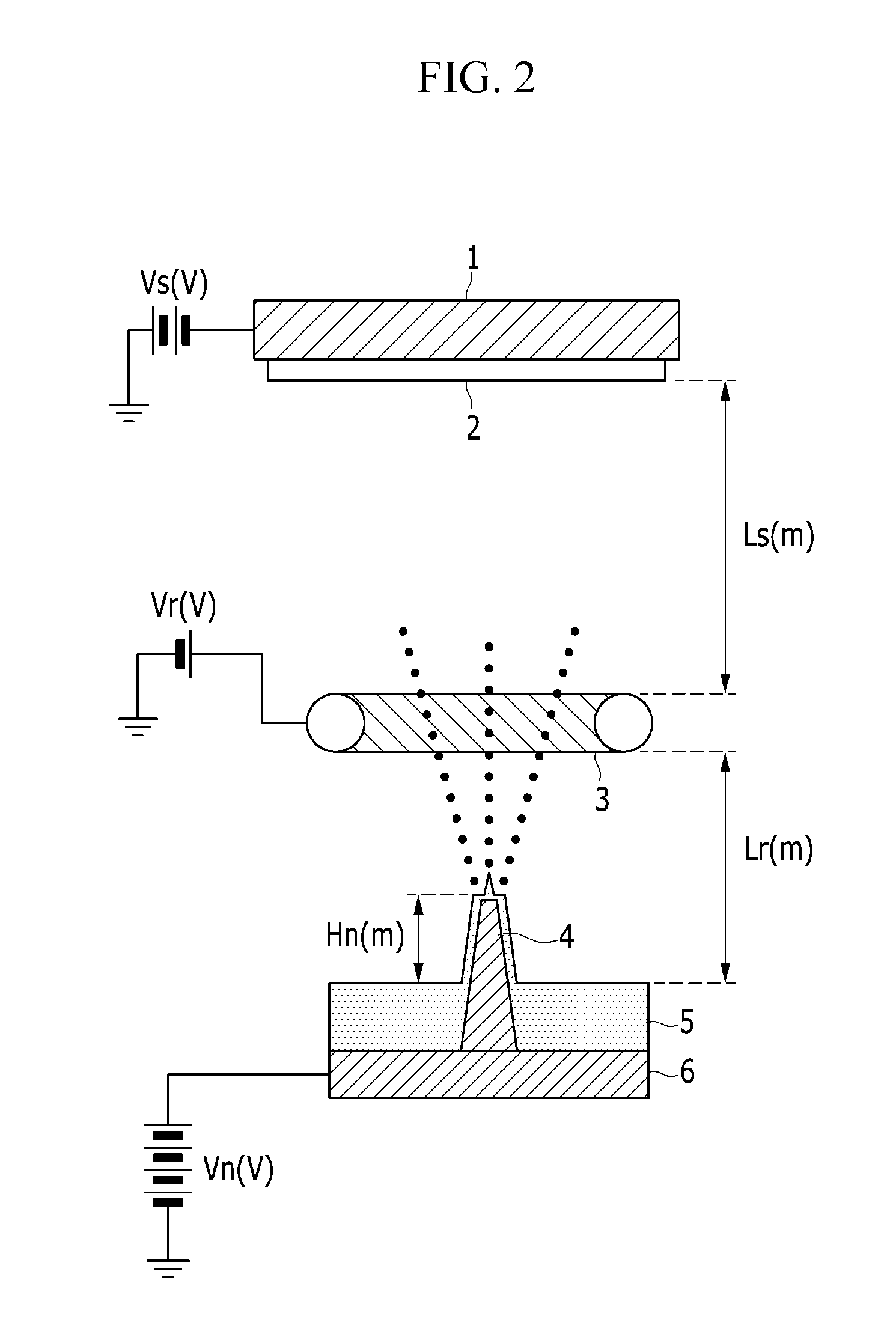
A thin film fabricating apparatus includes: an electrode bath which contains a thin film-forming material; a plurality of needle electrodes disposed in the electrode bath; a plurality of ring electrodes disposed on the electrode bath at positions corresponding to the needle electrodes; and a substrate stand disposed opposite to the needle electrodes and the ring electrodes, where the substrate stand holds the substrate, on which a thin film is to be formed.

Description


Claims


Application Information

Patent Timeline
Owner SAMSUNG ELECTRONICS CO LTD
Why Eureka
Try Eureka