Energy management system, display control apparatus, display method, and computer-readable storage medium

a technology of energy management and control apparatus, applied in the direction of computer control, process and machine control, instruments, etc., can solve the problems of difficult to focus on the relation between operating status and energy performance, and achieve the effect of easy comparison of energy performan

Active Publication Date: 2016-03-31
YOKOGAWA ELECTRIC CORP
View PDF3 Cites 3 Cited by
  • Summary
  • Abstract
  • Description
  • Claims
  • Application Information

AI Technical Summary

Benefits of technology

[0020]Embodiments of the present invention make it possible to easily compare the energy performance to be managed at the equivalent operating statuses.

Problems solved by technology

However, with the related-art energy management screen, it is difficult to focus on the relation of the operating status and the energy performance and compare the energy performance of the operating status which is equivalent in time series.

Method used


Image

  • Energy management system, display control apparatus, display method, and computer-readable storage medium
  • Energy management system, display control apparatus, display method, and computer-readable storage medium
  • Energy management system, display control apparatus, display method, and computer-readable storage medium

Examples


Embodiment Construction

[0034]Now an embodiment of the present invention is described with reference to the drawings.

[0035](Overall Configuration Related to an Energy Management System 100)

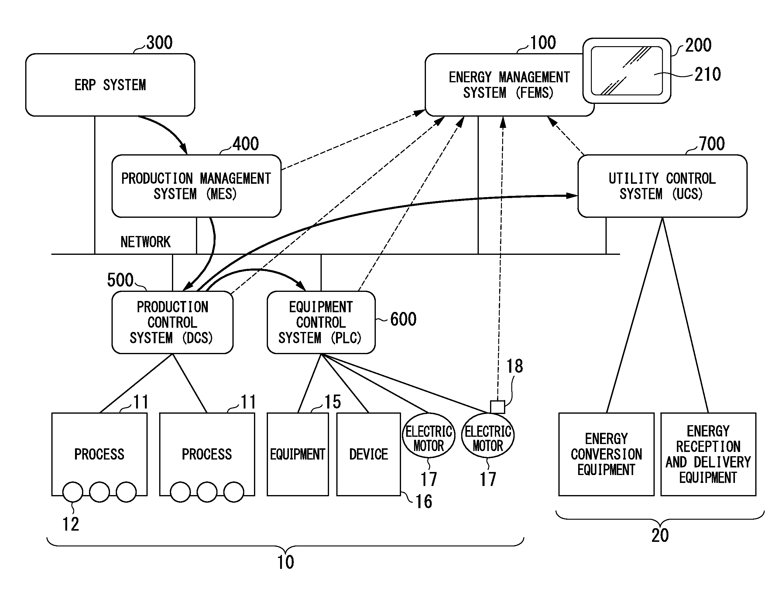
[0036]FIG. 1 is a configuration diagram illustrating one example of a configuration related to an energy management system 100 according to the present embodiment. This FIG. 1 shows a relationship between a configuration of various systems in a production factory 10 and the energy management system 100 which displays energy performance and information which are collected from these systems. The energy management system 100 is, for example, an energy management software system (FEMS), and is hereinbelow described in detail with reference to FIG. 3.

[0037]Here, the “energy performance” is called energy consumption, energy efficiency, etc., in the same manner as the definition of ISO50001. Moreover, “energy” refers to electricity, fuels, steam, heat, compressed air, and other like media in the same manner as the definition o...


PUM


Abstract

An energy management system is provided. The system includes an information collector which is configured to collect a first information in accordance with elapsing of time, including information on energy consumption of a subject of energy management or information on factors involved in a change of the energy consumption; and a display controller which is configured to collate a second information in which is included the first information, which is collected by the information collector, or specified energy performance for each second unit divided by one or a plurality of boundaries of an operating status which changes in accordance with the elapsing of time of the subject of energy management for each first unit which is divided by one or a plurality of physical or logical boundaries of the subject of energy management, based on the first information collected by the information collector to be the first unit and the second unit to cause the collated result to be displayed on a display.

Description

BACKGROUND OF THE INVENTION[0001]1. Field of the Invention[0002]Priorities are claimed on Japanese Patent Application No. 2014-195343, filed Sep. 25, 2014, the contents of which are incorporated herein by reference.[0003]Embodiments of the present invention relate to energy management systems, display control apparatuses, display methods, and computer-readable storage media.[0004]2. Related Art[0005]In recent years, efficient use of limited resources is highly demanded and energy saving actions are being actively promoted. To promote the energy saving, visualization of energy performance such as energy consumption, energy efficiency, etc., in equipment or facilities is important. For example, to find a deviation from a target value or to check the effect of energy saving actions, changes in the energy efficiency and the energy consumption of the equipment or facilities, the effect of the energy saving actions, etc., are displayed on an energy management screen.[0006]For example, the...

Claims


Application Information

Patent Timeline
Patent Type & Authority Applications(United States)
IPC IPC(8): G06T11/20G05B15/02G05F1/66G06T15/20
CPCG06T11/206G06T15/20G05F1/66G05B15/02
Inventor INOUE, KEN-ICHI
Owner YOKOGAWA ELECTRIC CORP
Why Eureka
Try Eureka