
Eye dropper positioning and guiding apparatus

a technology for positioning and guiding apparatuses, which is applied in the direction of medical atomisers, liquid dispensing, medical applicators, etc., can solve the problems of inability to accurately dispense medication into the eye, inability to properly position or align the eye drop applicator, and inadvertently waste medicine, etc., to achieve accurate dispense of medication into the eye

Active Publication Date: 2016-03-31
KING SAUD UNIVERSITY
View PDF0 Cites 1 Cited by
  • Summary
  • Abstract
  • Description
  • Claims
  • Application Information

AI Technical Summary

Benefits of technology

The apparatus enables precise administration of eye drops, reducing the risk of injury and infection by allowing for customizable positioning of the eye drop applicator, accommodating different nozzle designs and facial features, and ensuring accurate delivery of medication even for individuals with vision impairments or coordination challenges.

Problems solved by technology

Self-administration, for example, of eye drops using known eye drop applicators, however, can be challenging and can lead to injury for various reasons.
It can be difficult to properly position or align the eye drop applicator to administer eye drops at a particular location in relation to the eye while tilting the head back and simultaneously administering the eye drops.
This can result in inadvertently wasting medicine or, even worse, an inability to administer the correct dosage to the eye.
Further, the close positioning of a nozzle of an eye drop applicator in front of the eye can lead to missed judgment in the eye drop application, since objects relatively close to the eye can become blurred, and can thereby cause the nozzle of the eye drop applicator to come in contact with the corneal region of the eye as can potentially cause or increase the likelihood of infection, irritation or injury to the eye.
Also, such potential difficulties in eye drop administration can be more likely in individuals that experience reduced vision related to various eye conditions or coordination difficulties, such as hand tremors, as can hinder the ability to correctly position or aim the eye drop applicator, for example.
However, many of these known apparatuses for eye drop applicators can be selective in their application, as well as typically not being adapted to work with eye drop applicators having nozzles of a non-uniform design, size, or shape or nozzles of varying lengths, for example.
Therefore, such known apparatuses for eye drop applicators, when used for other than their intended selective application, can likely increase the likelihood that the nozzles that dispense the eye drops can come in contact with the corneal region of the eye, as can increase the possibility of damage to the eye.
Further, such known apparatuses for eye drop applicators can be difficult to adapt to work with individuals having different facial features (e.g. inter-pupillary distance and, the width and height of the nose) or individuals having bulging eyes or eyes below a relatively normal position because of possible difficulty or inability in achieving an acceptable position of an eye drop apparatus in relation to an eye prior to dispensing the medication.
Further, by not having a significant ability to allow for or provide an acceptable position of the eye drop applicator, various known apparatuses for eye drop applicators typically can have a reduced suitability for operated, injured, or inflamed eyes, since use of such known apparatuses can likely increase a possibility of the nozzle of the eye drop applicator coming into direct contact with the eye.
A likely result of such inadequacies and short comings of known apparatuses for eye drop applicators is that a relatively large majority of eye drops are generally applied or administered without using any positioning or guiding apparatus to position the eye drop applicator relative to the eye or other facial location.

Method used


Image

  • Eye dropper positioning and guiding apparatus
  • Eye dropper positioning and guiding apparatus
  • Eye dropper positioning and guiding apparatus

Examples


Embodiment Construction

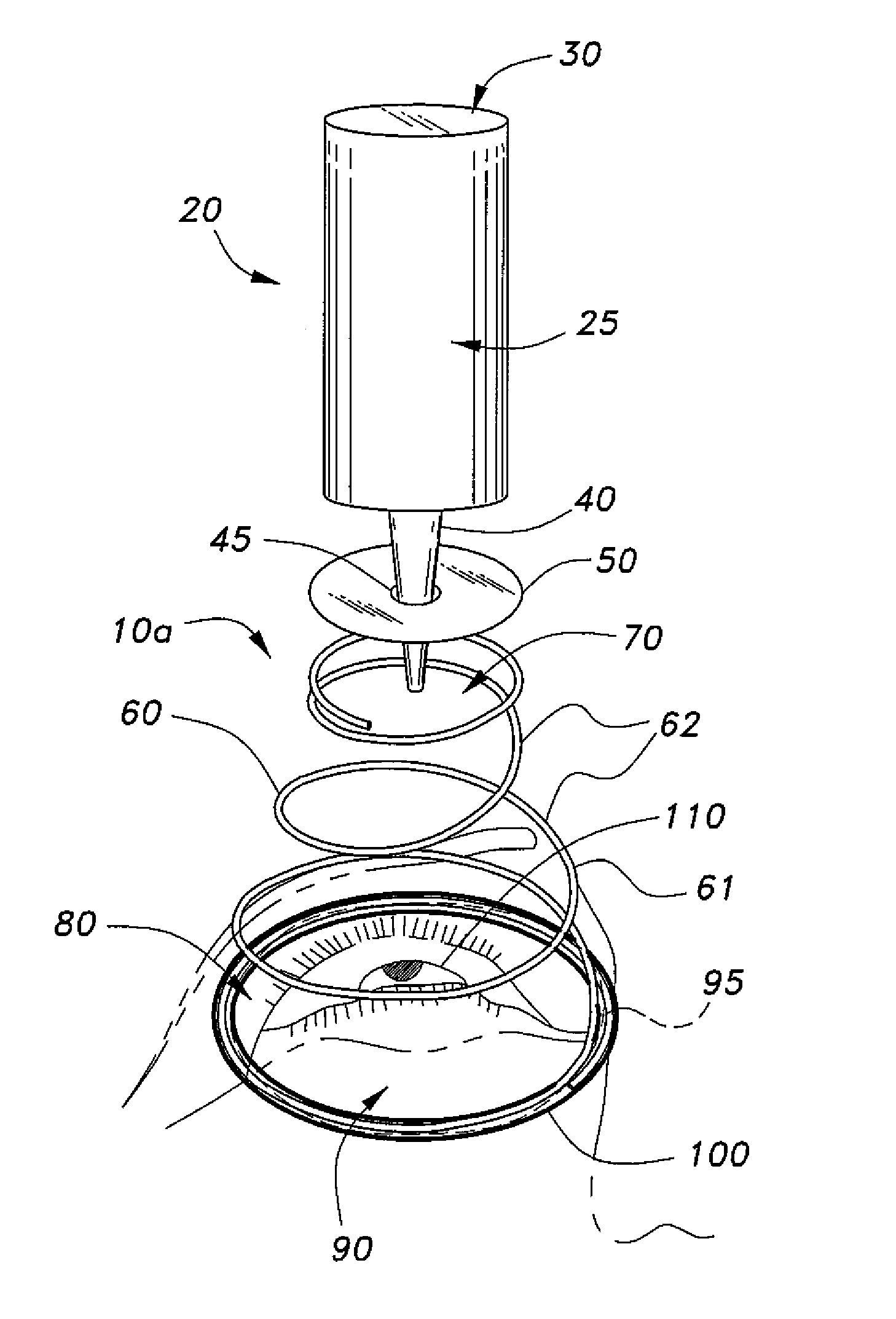
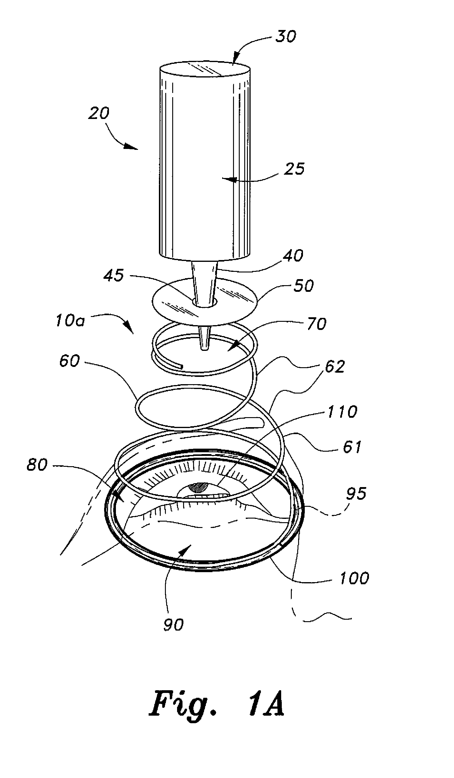
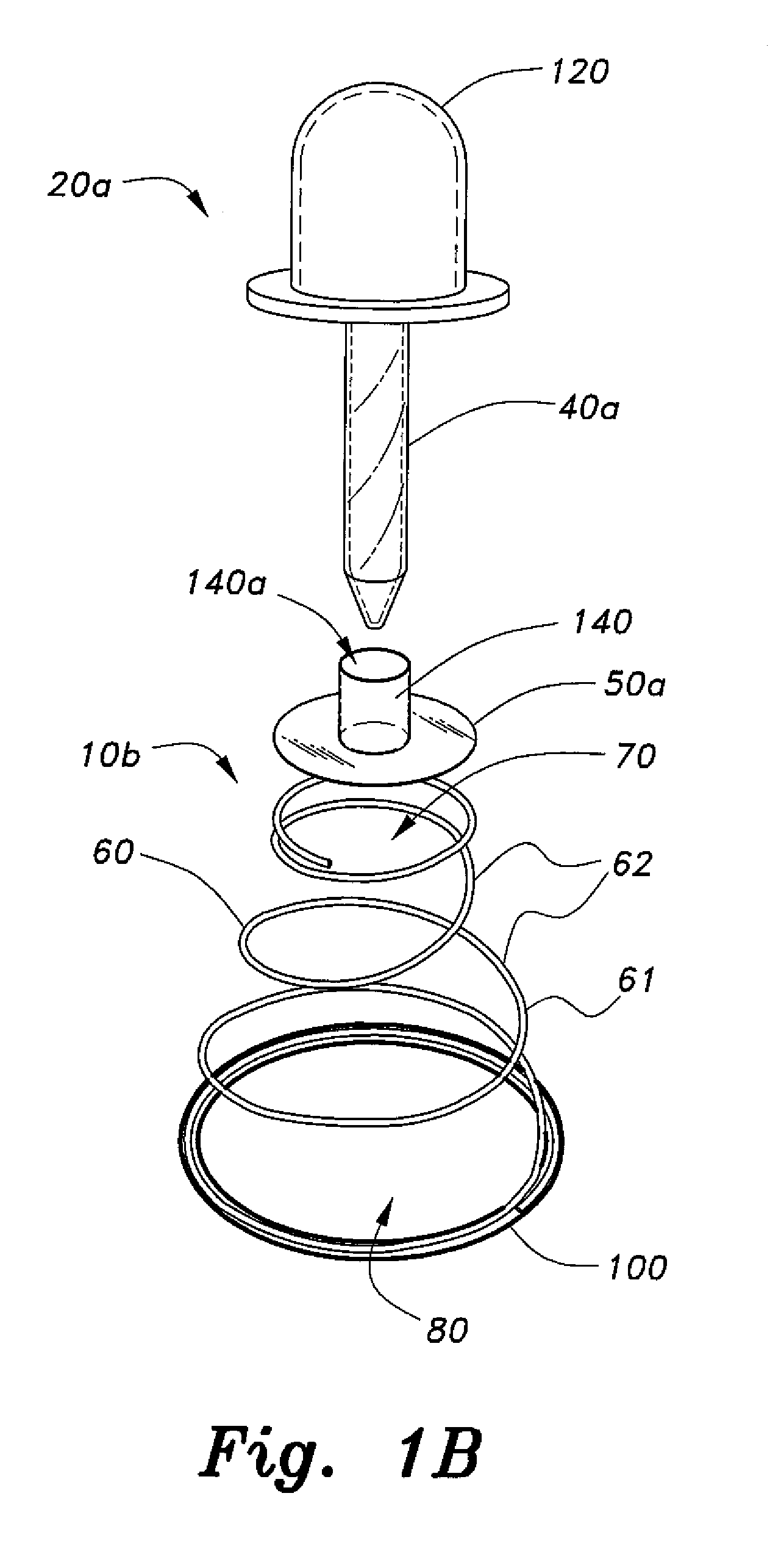
[0033]Referring to FIGS. 1A and 1B, the eye dropper positioning and guiding apparatuses 10a and 10b include a resilient guiding device 60 including a selectively compressible member 61 having a first opening 70 having a first diameter or a first crosswise dimension adapted to receive an eye drop applicator, such as eye drop applicators 20 and 20a, and a second opening 80 of a second diameter or a second crosswise dimension adapted to position an eye 110 within an area of the second opening 80 to receive a fluid from the eye drop applicator, such as eye drop applicators 20 and 20a. The fluid or eye drop(s) dispensed by the eye drop applicator, can include not only a liquid medication but also a cream / gel type or a salve type medication, as well, for example, and should not be construed in a limiting sense. During use, when the person administering the eye medication selectively moves a base 30 or a bulb 120 of an eye drop applicator, such as including one or more of vertical, lateral...


PUM


Abstract

The eye dropper positioning and guiding apparatus includes a resilient guiding device having a selectively compressible member having a first opening adapted to receive an eye drop applicator and a second opening adapted to position an eye within an area of the second opening to receive a fluid from the eye drop applicator. The selectively compressible member is adapted for selective linear and nonlinear movement in relation to the eye positioned within the area of the second opening. The eye dropper positioning and guiding apparatus can also include a support base and a resilient guiding device including a selectively expandable member having a plurality of concentric loops having an outermost loop and an innermost loop, adapted for selective linear and nonlinear movement, or a support base and a resilient guiding device including a plurality of concentric, interconnected rings adapted for selective linear and nonlinear movement in relation to an eye.

Description

CROSS REFERENCE TO RELATED APPLICATIONS[0001]This is a divisional of our prior application Ser. No. 14 / 497,279, filed Sep. 25, 2014, now pending.BACKGROUND OF THE INVENTION[0002]1. Field of the Invention[0003]The present invention relates to an apparatus to position and guide an eye drop applicator to improve the accuracy when administering eye drops into an eye. More specifically, the present invention allows for one or more of selective linear and nonlinear movement to selectively adjust a height and a position of an eye drop applicator in relation to an eye, such as including one or more of vertical, lateral, oblique, and various combinations, paths and directions of movement of the eye drop applicator, to aid in the administration of an eye drop into an eye and to aid in protecting the eye from contact with the nozzle of the eye drop applicator.[0004]2. Description of the Related Art[0005]Many people use eye drops as treatment for microbial infections, glaucoma, dry eye syndrome...

Claims


Application Information

Patent Timeline
Patent Type & Authority Applications(United States)
IPC IPC(8): A61F9/00
CPCA61F2250/0004A61M35/00A61F9/0008A61M11/007A61M11/00A61F9/0026A61M11/006A61H35/02A61M2210/0612A61M11/008A61M35/003A61F2230/0091B65D47/18B65D47/185B65D83/30F16F1/027F16F2234/06F16F2238/022
Inventor ALAM, MOHD, AFTABAL-JENOOBI, FAHAD, IBRAHIMAL-MOHIZEA, ABDULLAH, M.
Owner KING SAUD UNIVERSITY
Learn More