
Systems and methods for reducing bleed emissions

a technology of bleed emissions and systems, applied in the direction of combustion air/fuel air treatment, electric control, instruments, etc., can solve the problems of limited airflow through the canister, inability to completely clear the contents of limited opportunities for purging the fuel vapor canister, etc., to achieve the effect of reducing the bleed emissions of the fuel system, and reducing the cost of bleed emissions

Active Publication Date: 2016-03-24
FORD GLOBAL TECH LLC
View PDF15 Cites 13 Cited by
  • Summary
  • Abstract
  • Description
  • Claims
  • Application Information

AI Technical Summary

Benefits of technology

The patent text describes a system and method for reducing bleed emissions in vehicles, which can occur when fuel vapor is purged from a canister and enters the engine intake. The system includes a fuel vapor canister, an air pump, and a controller that activates the air pump to redistribute fuel vapor away from the canister and reduce bleed emissions. This allows vehicles to meet stringent emissions standards, even when they are parked in warm or sunny conditions for multiple diurnal cycles. The system also includes a hydrocarbon sensor to detect canister breakthrough and activate the vacuum pump accordingly. Overall, the system helps to prevent bleed emissions and improve fuel efficiency in vehicles.

Problems solved by technology

Hybrid vehicles, and other vehicles configured to operate with minimal or no intake vacuum may have limited opportunities to purge the fuel vapor canister.
Even in standard engine vehicles, the fuel vapor canister may not be completely cleared of contents following a purge, as the airflow through the canister is not uniform.
If the vehicle is parked in a hot or sunny location over a diurnal cycle, the retained hydrocarbons may desorb from the canister and result in bleed emissions.
However, this adds additional cost, weight, and packaging to the vehicle.
Even with a bleed canister, a car parked outside for multiple diurnal cycles may experience bleed from the bleed canister itself.
Further, in hybrid vehicles, a highly restrictive bleed canister may impede fuel tank depressurization prior to a refueling sequence.

Method used


Image

  • Systems and methods for reducing bleed emissions
  • Systems and methods for reducing bleed emissions
  • Systems and methods for reducing bleed emissions

Examples


Embodiment Construction

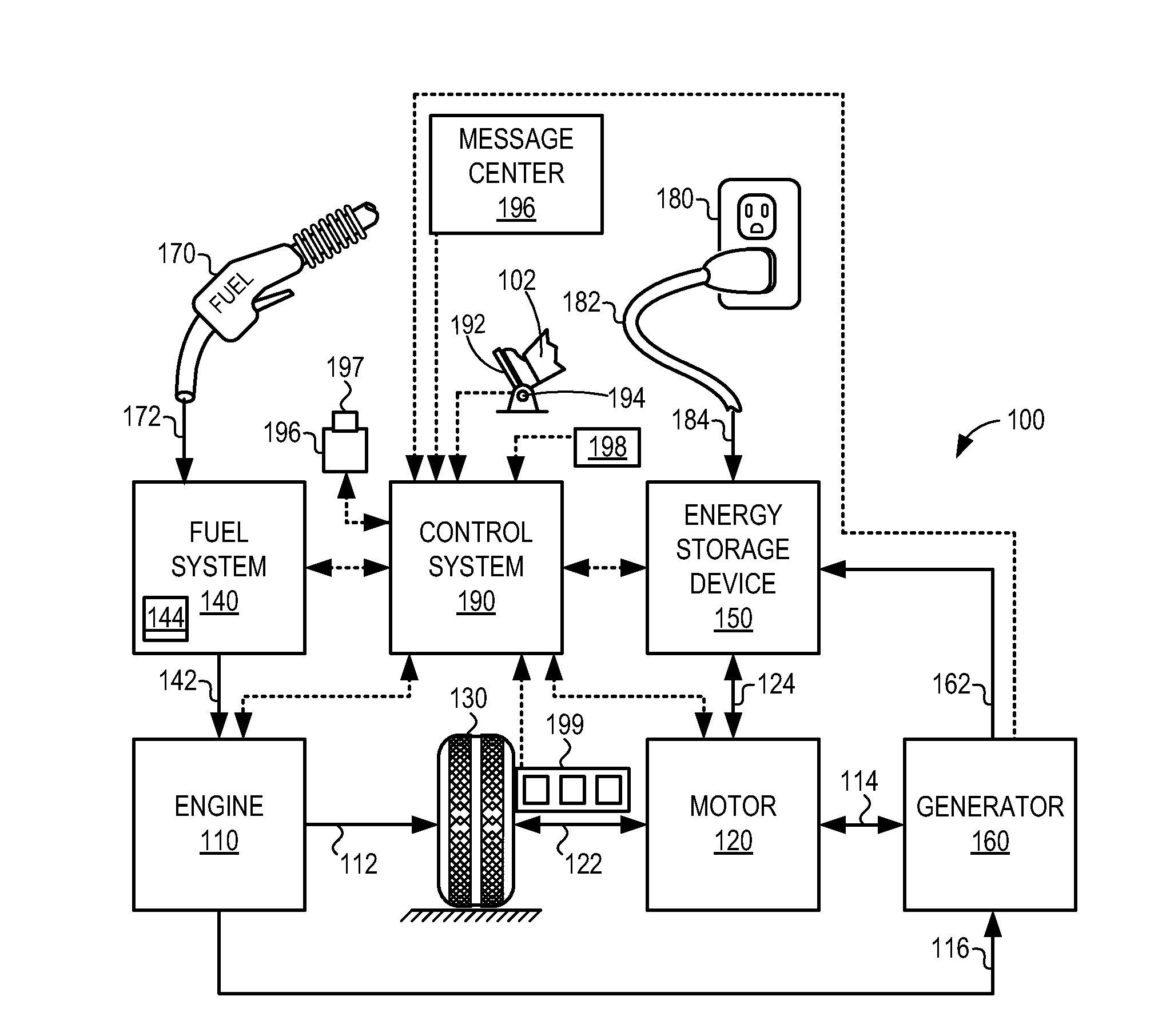
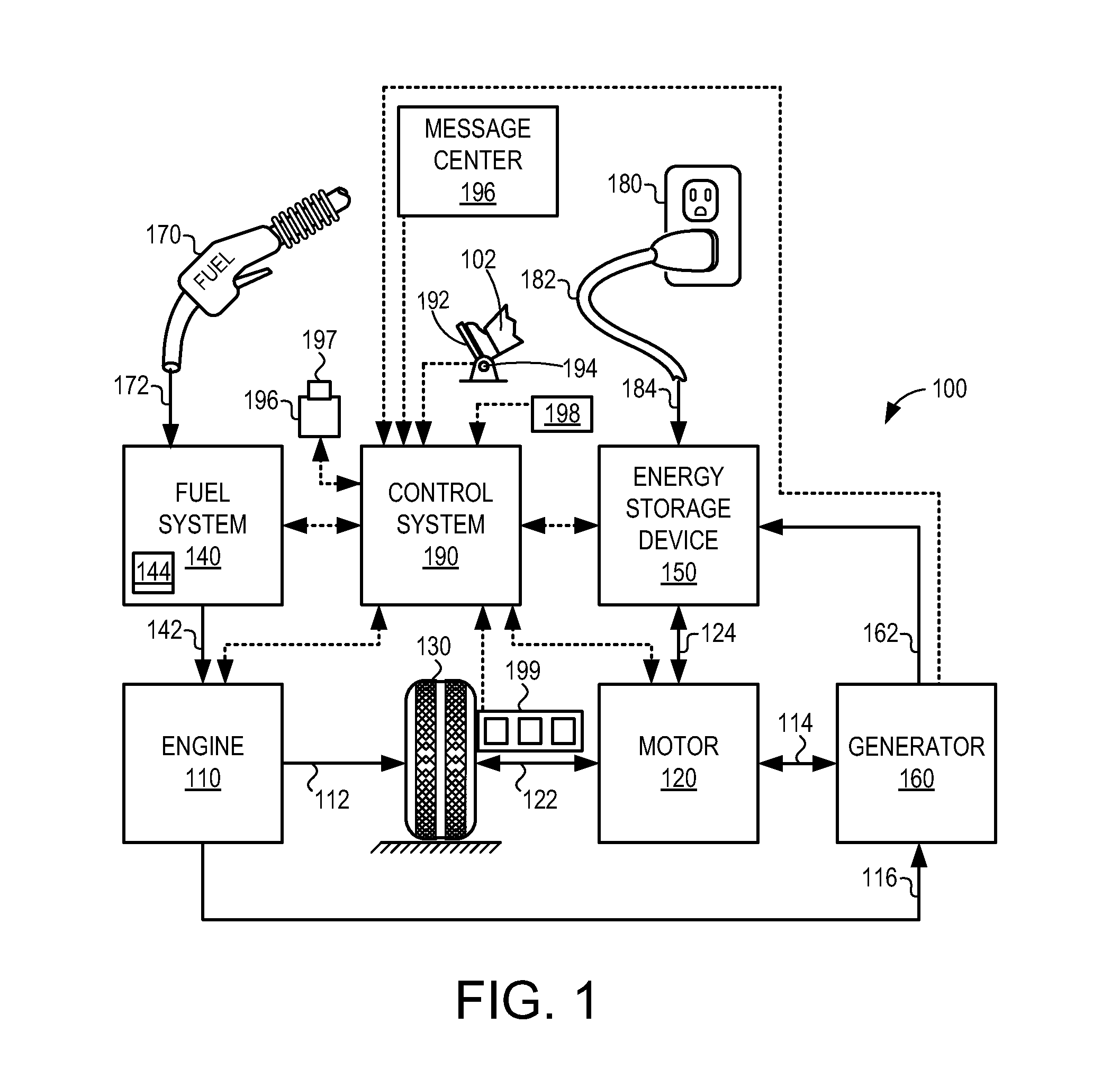
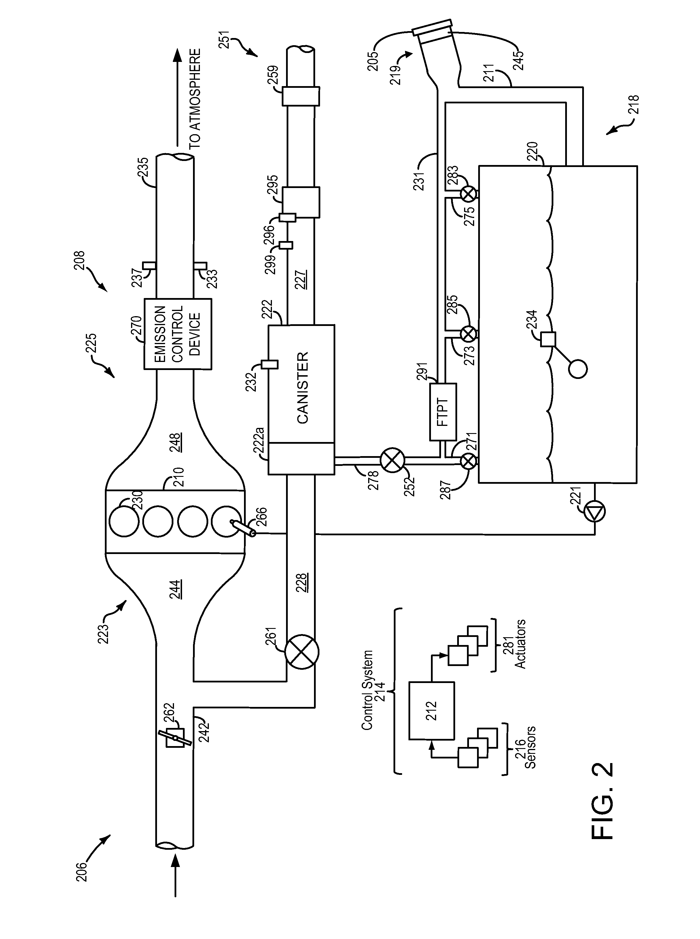
[0023]This detailed description relates to systems and methods for reducing bleed emission in fuel systems. Specifically, this description relates to systems and methods for redistributing fuel vapor within a fuel vapor canister during a vehicle-off condition. The fuel vapor canister may be included in a plug-in hybrid vehicle (PHEV), such as the PHEV schematically depicted in FIG. 1. The fuel vapor canister may be included in an evaporative emissions system coupled to a fuel system, as shown schematically in FIG. 2. The evaporative emissions system may include an evaporative leak check module (ELCM), operable in multiple conformations, such as the conformations shown in FIGS. 3A-3D. Using the systems of FIGS. 1, 2, and 3A-3D, bleed emissions may be managed by the example method shown in FIG. 4. A timeline for a bleed emissions management operation using the method of FIG. 4 is shown in FIG. 5. In some examples, the evaporative emissions system may be configured to reverse air flow ...


PUM


Abstract

A method for a fuel system, comprising: during a first condition, including an engine-off condition and a sealed fuel tank, directing fresh air into a fuel vapor canister responsive to detecting hydrocarbons in a canister vent line. By directing fresh air into the fuel vapor canister, fuel vapor stored within the canister may be redistributed away from the canister vent line. In this way bleed emissions from the fuel system may be reduced without the need for a dedicated bleed canister.

Description

BACKGROUND AND SUMMARY[0001]Vehicles sold in North America are required to adsorb refueling, diurnal and running loss vapors into a carbon canister. When the canister is loaded with fuel vapor, the contents may be purged to engine intake using engine intake vacuum to draw fresh air though the canister, desorbing bound hydrocarbons. Strict regulations regulate the performance of evaporative emissions systems.[0002]Hybrid vehicles, and other vehicles configured to operate with minimal or no intake vacuum may have limited opportunities to purge the fuel vapor canister. Even in standard engine vehicles, the fuel vapor canister may not be completely cleared of contents following a purge, as the airflow through the canister is not uniform. If the vehicle is parked in a hot or sunny location over a diurnal cycle, the retained hydrocarbons may desorb from the canister and result in bleed emissions.[0003]Bleed emissions may be limited by adding a secondary “bleed” canister to capture desorbe...

Claims


Application Information

Patent Timeline
Patent Type & Authority Applications(United States)
IPC IPC(8): F02D41/00F02M25/08
CPCF02D41/004F02M25/0809F02M25/0854F02M25/0836B60W20/00F02D41/042F02D41/0032F02D41/0045B60K15/03504B60K15/03519F02M25/0818F02M25/089B60W20/15F02D41/0035
Inventor DUDAR, AED, M.
Owner FORD GLOBAL TECH LLC
Learn More