Weight plate locking hub

a technology of locking hub and weight plate, which is applied in the direction of weights, gymnastic exercise, sport apparatus, etc., can solve the problems of increased risk to users, increased risks to users, and limited space between exercise equipment,

Inactive Publication Date: 2016-03-24
BEHLE S TYLER
View PDF0 Cites 7 Cited by
  • Summary
  • Abstract
  • Description
  • Claims
  • Application Information

AI Technical Summary

Benefits of technology

[0008]In yet another non-limiting embodiment, a method of use of a locking hub as described herein includes providing a locking hub according to the present disclosure in an unlocked state and positioning the locking hub on a bar or other object extending through an axis of the locking hub. The method includes rotating a first hub of the locking hub relative to a sleeve and compressing a pad against the bar or other object and thereby restricting or substantially preventing lateral movement of the locking hub relative to the bar or other object.

Problems solved by technology

Lateral movement of the weight plates before and / or during the exercise may make the bar more difficult for a user to control during the exercise and may create additional risks to the user, individuals in the vicinity, or surrounding objects.
In a fitness center or gym, the space between exercise equipment may be limited.
A poorly-controlled bar and / or weights may create a hazard to the user or other individuals in the gym.
In the case of commercial gyms, the increased risk created by a poorly-controlled bar and / or weights may, in turn, increase liability for the gym.
However, the complete removal of the bar clamps from the bar each time a user removes or changes the weight plates increases the chance that the bar clamps may be lost or broken.
Additionally, to save costs and reduce clutter, gyms typically have a limited number of bar clamps available for use.
Additionally, bar clamps and spring clamps can become stiff, thereby making them difficult for users to properly place and secure on the bar.

Method used


Image

  • Weight plate locking hub
  • Weight plate locking hub
  • Weight plate locking hub

Examples


Embodiment Construction

[0022]One or more specific embodiments of the present disclosure will be described below. In an effort to provide a concise description of these embodiments, some features of an actual embodiment may be described in the specification. It should be appreciated that in the development of any such actual embodiment, as in any engineering or design project, numerous embodiment-specific decisions will be made to achieve the developers' specific goals, such as compliance with system-related and business-related constraints, which may vary from one embodiment to another. It should further be appreciated that such a development effort might be complex and time consuming, but would nevertheless be a routine undertaking of design, fabrication, and manufacture for those of ordinary skill having the benefit of this disclosure.

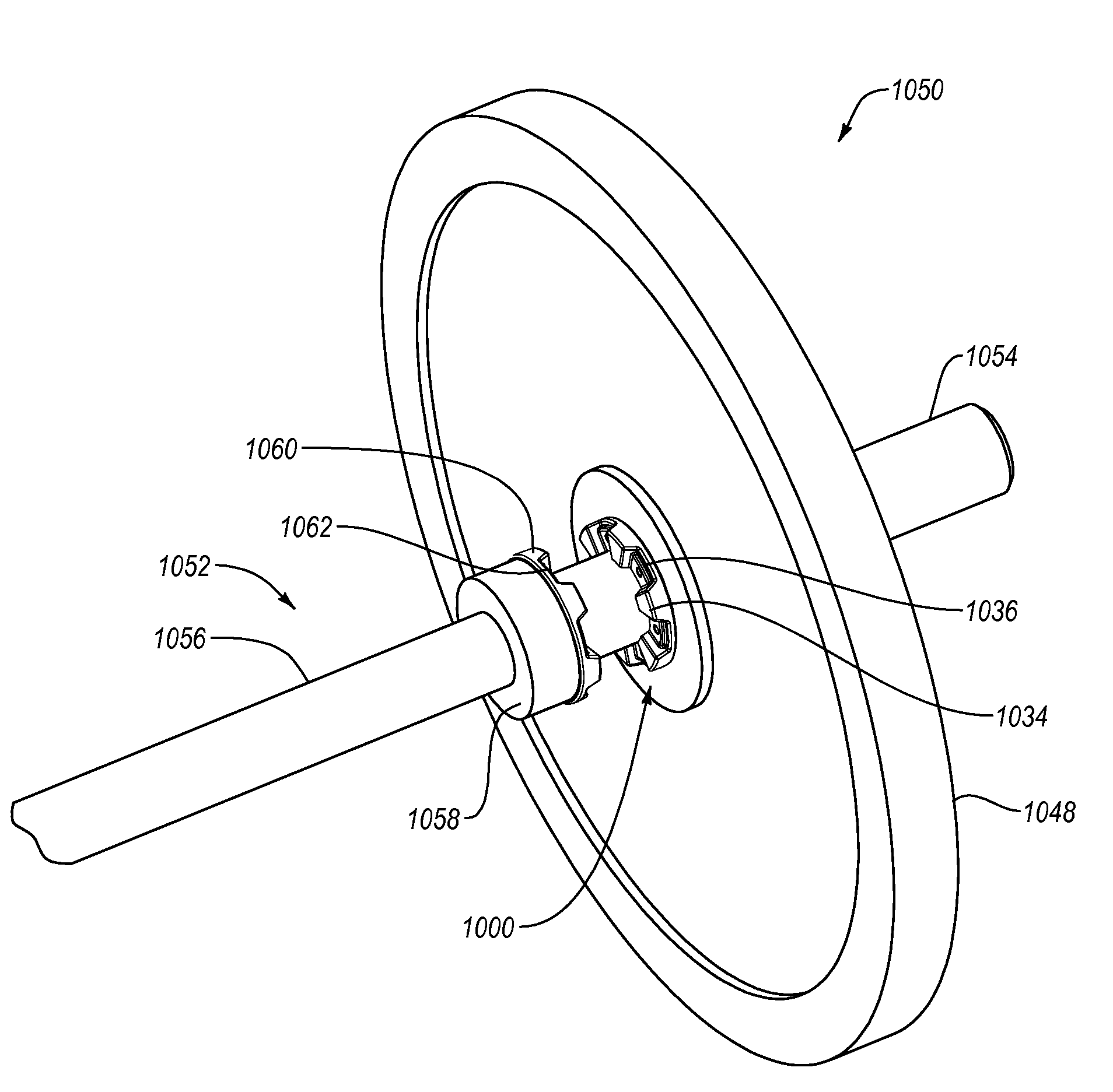
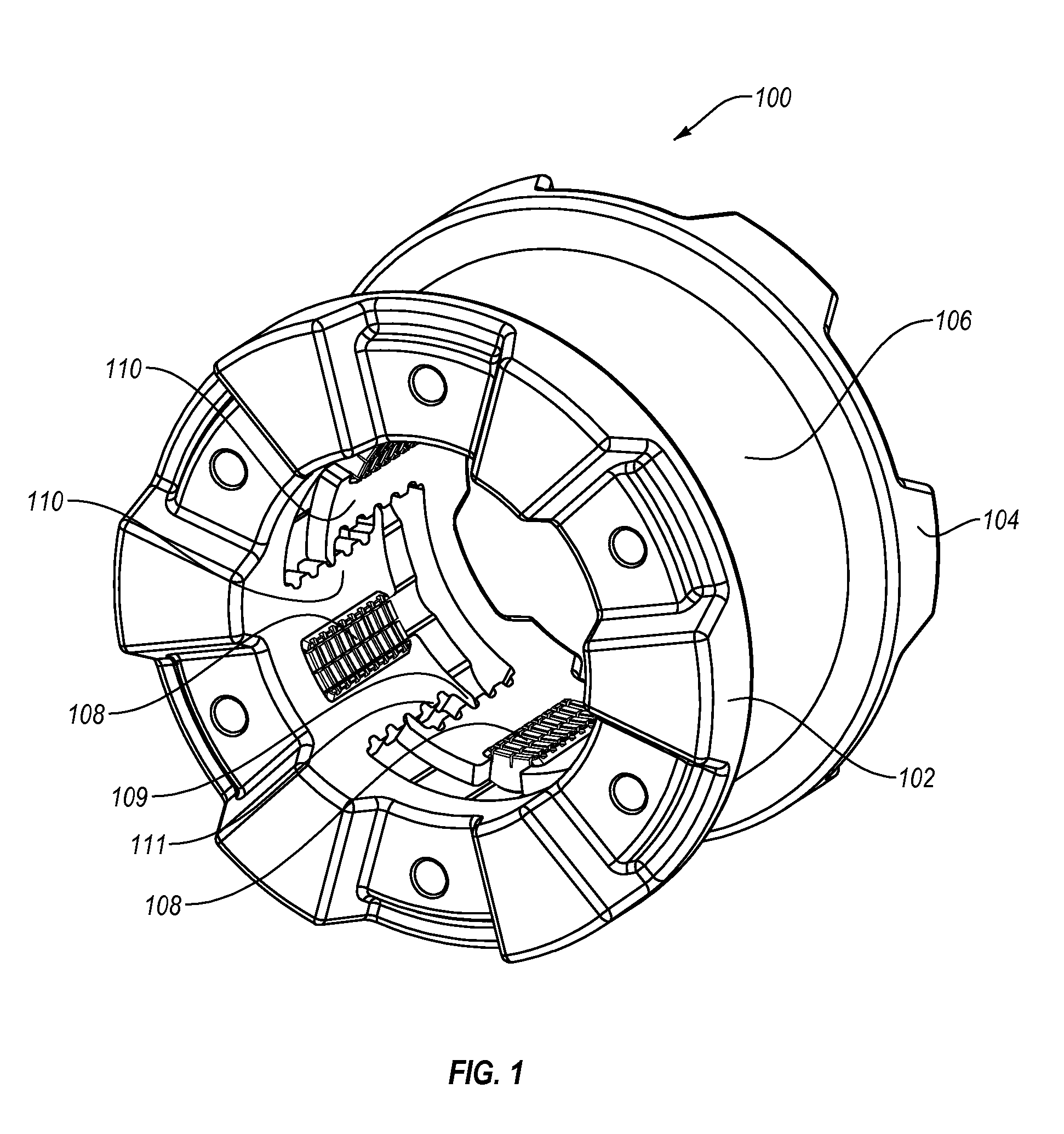
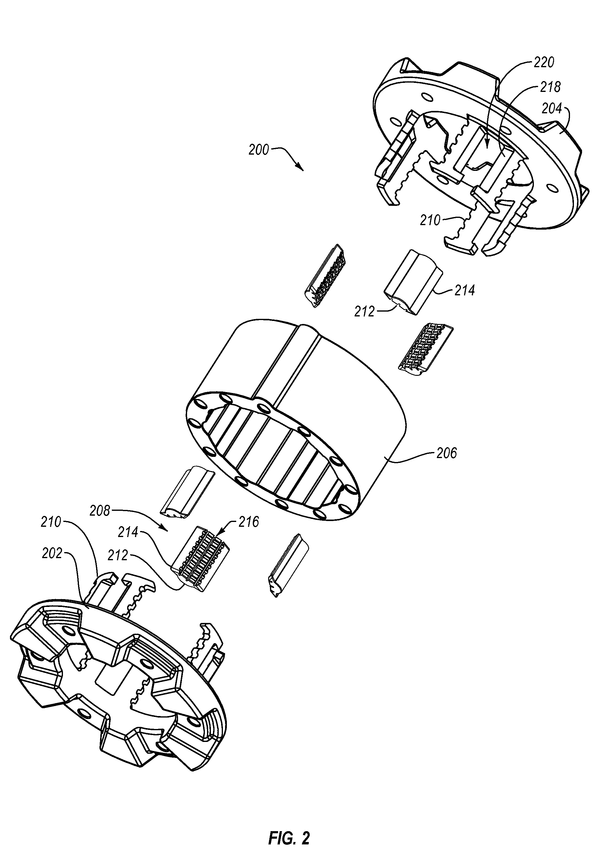
[0023]One or more embodiments of the present disclosure may generally relate to securing an object about a bar located therethrough. More particularly, one or more embodim...


PUM


Abstract

Implementations of the present invention relate to devices, systems, and methods for the safe and efficient use of exercise equipment and, in particular, weight training equipment. A locking hub for weight training equipment may include a first hub and second hub, the first hub and second hub having a sleeve located therebetween. The first hub and/or second hub may hold one or more pads adjacent the sleeve. Rotation of the sleeve relative to the first hub and/or the second hub may compress the one or more pads to force the pads radially inward against a weight bar, substantially restricting movement of the locking hub relative to the weight bar.

Description

CROSS-REFERENCE TO RELATED APPLICATIONS[0001]N / ABACKGROUND OF THE DISCLOSURE[0002]Free weights provide weight resistance during strength training exercises. For example, a strength training device or system may include a bar having a grip in the center and weight loading areas on either side of the grip. A user may load one or more weight plates onto the weight loading areas to increase the weight of the bar. The user may load the weight plates onto the bar such that there is an equal weight distribution on either side of the grip. An equal weight distribution will minimize the torque placed on the bar and balance the bar during the weight training exercises. Lateral movement of the weight plates before and / or during the exercise may make the bar more difficult for a user to control during the exercise and may create additional risks to the user, individuals in the vicinity, or surrounding objects.[0003]In a fitness center or gym, the space between exercise equipment may be limited....

Claims


Application Information

Patent Timeline
Patent Type & Authority Applications(United States)
IPC IPC(8): A63B21/072
CPCA63B21/0728A63B21/0724A63B2071/0694A63B2225/09A63B2209/08
Inventor BEHLE, S., TYLERCOOK, RYAN, D.
Owner BEHLE S TYLER
Why Eureka
Try Eureka