
Hammertoe implant and instrument

a technology of hammertoe implants and instruments, applied in the field of orthopedic surgery, can solve problems such as multiple surgeries, pin tract infections, and pain in the toes or feet, and achieve the effects of improving the quality of li

Active Publication Date: 2016-03-24
WRIGHT MEDICAL TECH
View PDF3 Cites 17 Cited by
  • Summary
  • Abstract
  • Description
  • Claims
  • Application Information

AI Technical Summary

Benefits of technology

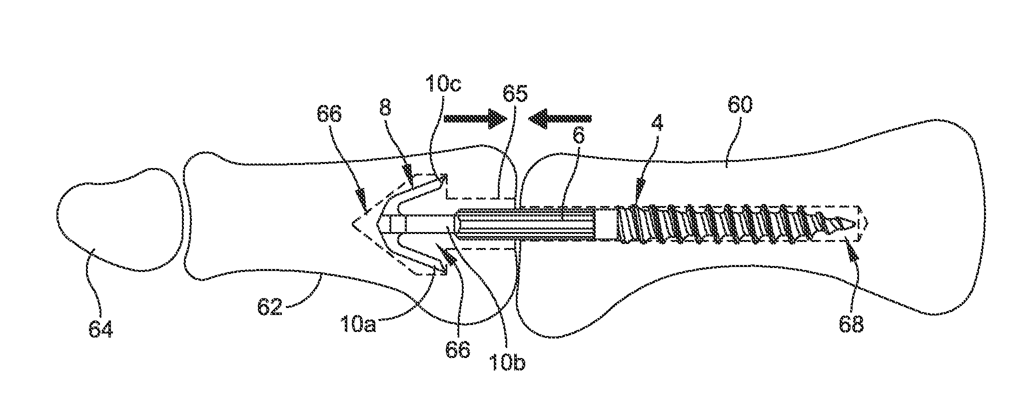
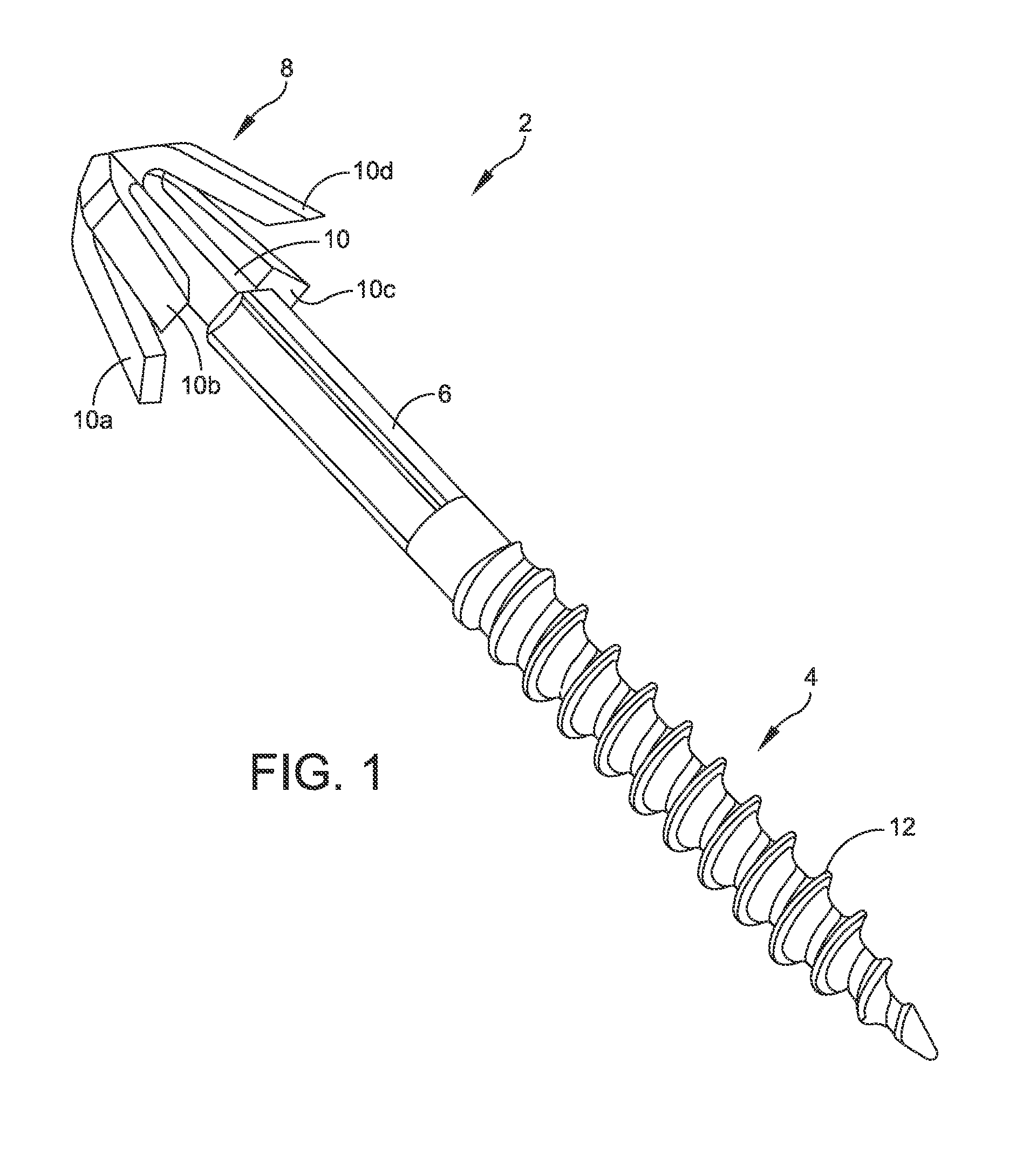
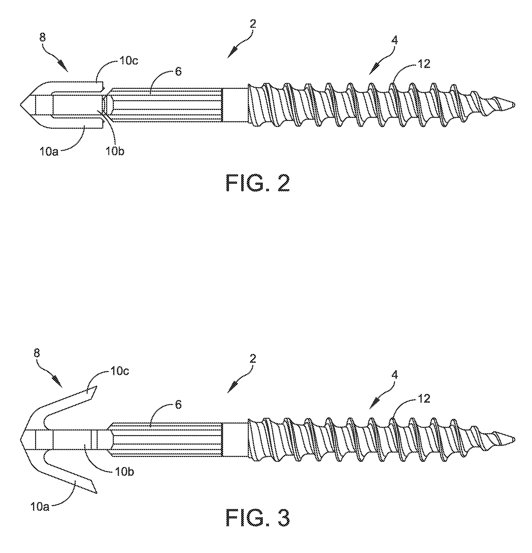
The present patent text describes a new type of bone implant called a hammertoe implant, which can be used to correct hammertoe and related foot maladies. The hammertoe implant has a unique design with an expandable section that can be inserted into a reverse countersink in a second bone, allowing for easy and accurate placement. The method of inserting the implant is simple and can be easily performed using a surgical tool. The technical effects of this invention include the ability to provide improved and more targeted correction of hammertoe and related foot maladies, which can help to alleviate pain and improve quality of life for patients.

Problems solved by technology

Persons with hammertoe may also have corns or calluses on the top of the middle joint of the toe or on the tip of the toe and may feel pain in their toes or feet while having difficulty finding comfortable shoes.
As a result, K-wires often lead to pin tract infections, loss of fixation, and other conditions.
Additional disadvantages of K-wires include migration and breakage of the K-wires thus resulting in multiple surgeries.
Due to the various disadvantages of using K-wires, however, compression screws are being employed as an implant alternative.
Further, with the use of screw implants, a patient may wear normal footwear shortly after the respective surgery.
Among other disadvantages, both kinds of known implants result in an undesirable pistoning effect, i.e., part or all of the implant will toggle or move within the bone as the patient's toe moves.
Pistoning decreases the stability of the implant and lessens the compression across the joint.
Moving parts, such as fittings, hinges, expansion pieces, and the like also decrease the stability, lifespan, and compression force of the implant.

Method used


Image

  • Hammertoe implant and instrument
  • Hammertoe implant and instrument
  • Hammertoe implant and instrument

Examples


Embodiment Construction

[0030]The description of the exemplary embodiments is intended to be read in connection with the accompanying drawings, which are to be considered part of the entire written description. In the description, relative terms such as “lower,”“upper,”“horizontal,”“vertical,”“above,”“below,”“up,”“down,”“top” and “bottom,” as well as derivatives thereof (e.g., “horizontally,”“downwardly,”“upwardly,” etc.) should be construed to refer to the orientation as then described or as shown in the drawing under discussion. These relative terms are for convenience of description and do not require that the apparatus be constructed or operated in a particular orientation. Terms concerning attachments, coupling and the like, such as “connected” and “interconnected,” refer to a relationship wherein structures are secured or attached to one another either directly or indirectly through intervening structures, as well as both movable or rigid attachments or relationships, unless expressly described other...


PUM


Abstract

A bone implant comprising an elongate body having a first end and a second end coupled by a shaft is disclosed. The first portion is configured to couple to a first bone. The second portion comprises a first expandable section comprising at least one expandable feature. The first expandable section is configured to be received within a reverse countersink in a second bone in a collapsed state and to expand within the reverse countersink. The expandable feature couples to a bearing surface of the reverse countersink. A surgical tool comprising a shaft and at least one expandable cutting edge is disclosed. The shaft is sized and configured to be received within a canal formed in a bone. The expandable cutting edge is formed integrally with the shaft. The expandable cutting edge is configured to expand from a collapsed position to an expanded position for forming a reverse countersink.

Description

FIELD OF THE INVENTION[0001]This disclosure generally relates to systems and methods for orthopedic surgery. More particularly, this disclosure relates to systems and methods for hammertoe implants.BACKGROUND[0002]A hammertoe, or contracted toe, is a deformity of the proximal inter-phalangeal joint of the second, third, or fourth toe causing the toe to be permanently bent and giving the toe a semblance of a hammer. Initially, hammertoes are flexible and may be corrected with simple measures but, if left untreated, hammertoes may require surgical intervention for correction. Persons with hammertoe may also have corns or calluses on the top of the middle joint of the toe or on the tip of the toe and may feel pain in their toes or feet while having difficulty finding comfortable shoes.[0003]One method of treatment may include correction by surgery if other non-invasive treatment options fail. Conventional surgery usually involves inserting screws, wires or other similar implants in toe...

Claims


Application Information

Patent Timeline
IPC IPC(8): A61B17/72A61B17/16A61F2/42
CPCA61B17/7291A61B17/7266A61F2002/423A61B17/1604A61F2/4225A61B17/1682A61B17/1617A61B17/1686A61B17/7283A61B17/8872A61F2002/4228
Inventor MCCORMICK, DANIEL, F.
Owner WRIGHT MEDICAL TECH
Learn More