Needle positioning apparatus

a positioning apparatus and needle technology, applied in the field of medical devices, can solve the problems of long trial and error routine, deleterious to patients, and difficult to position the needle with respect to the target by a single puncturing process

Active Publication Date: 2016-03-17
CANON USA +1
View PDF4 Cites 28 Cited by
  • Summary
  • Abstract
  • Description
  • Claims
  • Application Information

AI Technical Summary

Benefits of technology

[0011]A positioning apparatus according to some embodiments of the present invention includes a needle holder having a through hole that is adapted to at least partially surround a needle to guide the needle in a longitudinal direction; a needle positioning unit having a base part adapted for mounting on a patient and a moving part having at least two degrees of freedom, which holds the needle holder and moves together with the needle holder so as to position the needle holder, and an engagement member that fixes a position of the needle holder with respect to the needle positioning unit. This can be accomplished either by the engagement member being at least partially detachably attached to the needle positioning unit or the needle holder being at least partially detachably attached to the engagement member. Thus, the positioning apparatus is able to regulate a movement direction of the needle where the needle, or needles, may be attached and detached by a physician during use.

Problems solved by technology

This process often requires a lengthy trial and error routine, which can be deleterious to the patient.
In puncture treatment in which such a modality is used as a visualization unit, it is often difficult to position the needle with respect to the target by a single puncturing process.
If a second or additional needle is needed, the previously inserted needle is clamped between the drive roller and the passive roller and will interfere with the second or additional needle being inserted.
Therefore, in multiple-needle puncture, positioning of the subsequently inserted needles cannot be performed with this apparatus.
However, an apparatus for multiple needle placements is not provided in this apparatus.

Method used


Image

  • Needle positioning apparatus
  • Needle positioning apparatus
  • Needle positioning apparatus

Examples


first embodiment

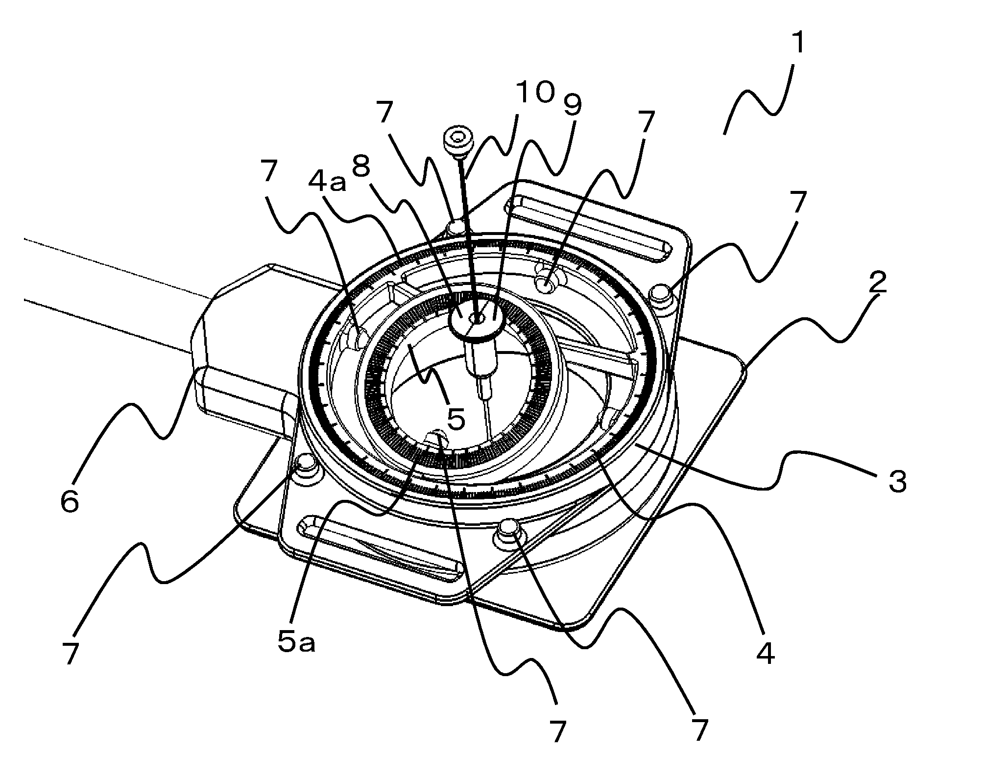
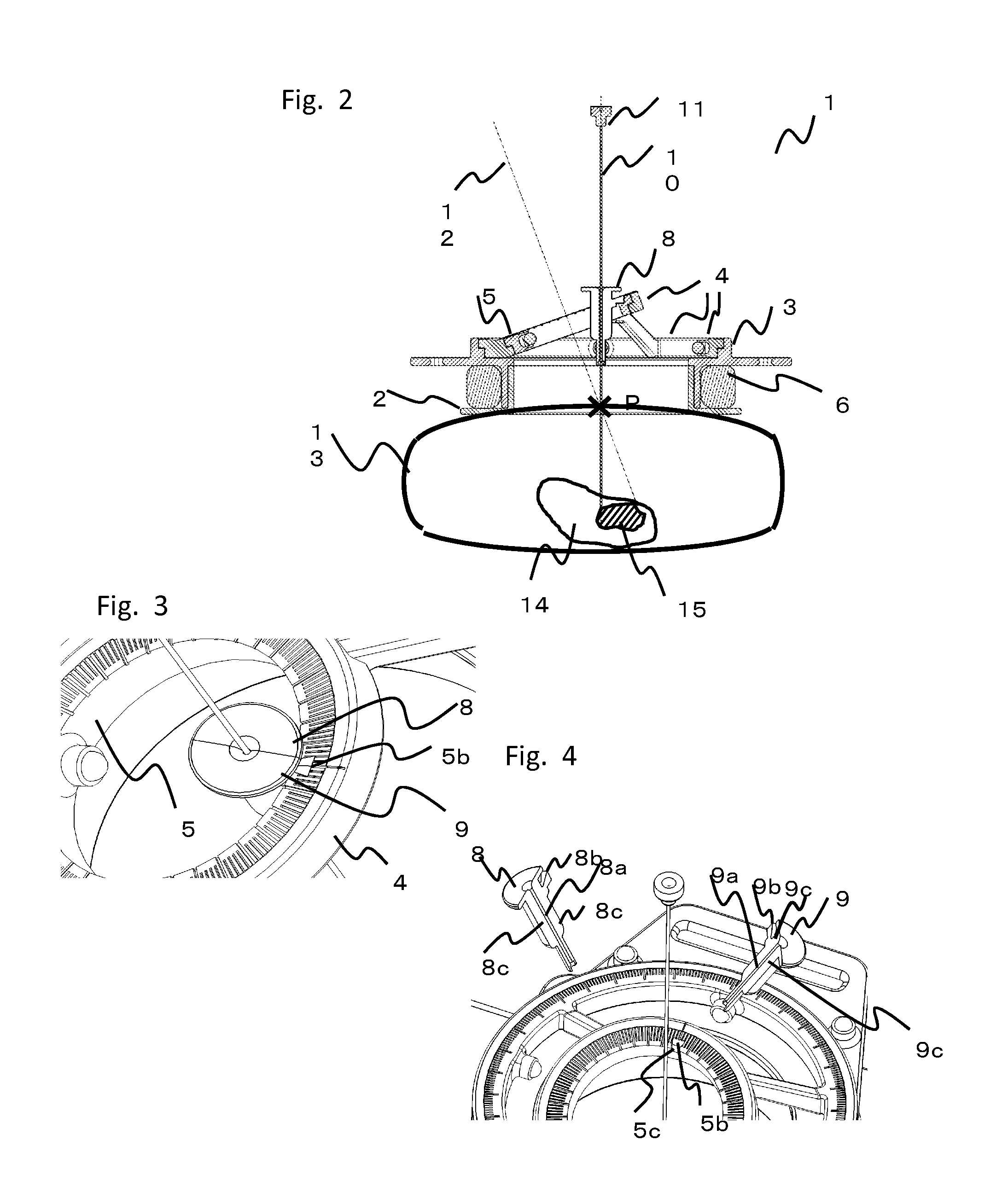
[0078]A first embodiment will now be described with reference to FIGS. 1 to 5. FIGS. 1, 3, and 4 are schematic perspective views of a needle positioning apparatus 1 according to the first embodiment. FIG. 2 is a schematic sectional view of the needle positioning apparatus 1 illustrating the manner in which puncture operation is performed by using the needle positioning apparatus 1. The needle positioning apparatus 1 according to the present embodiment is a remote-center-of-motion (RCM) mechanism having two rotational degrees of freedom. The detailed structure of the needle positioning apparatus 1 will now be described. In the present embodiment, an MRI unit is used as a visualization unit for the needle positioning apparatus 1.

[0079]Referring to the figures, the needle positioning apparatus 1 includes a mounting portion 2 which attaches to a human body 13. A base 3 is attached to the mounting portion 2. A guiding mechanism including a rail, a bearing, etc., used to move a first rota...

second embodiment

[0098]A second embodiment will now be described with reference to FIGS. 6 to 11. Components similar to those of the first embodiment are denoted by the same reference numerals, and descriptions thereof are thus omitted. FIG. 6 is a schematic perspective view of a needle positioning apparatus 21 according to the second embodiment.

[0099]Needle holders, which are needle holding units, will now be described in detail with reference to the drawings. Similar to the first embodiment, a second rotating member 25, which is rotatable relative to a first rotating member 4, is provided on the first rotating member 4. As illustrated in schematic perspective views of FIGS. 7 and 8, needle holder members 28 and 29, which are needle holding units, are provided on the second rotating member 25. The needle holder members 28 and 29 respectively include semicylindrical retaining portions 28b and 29b (fixing members of the needle holders) and divided portions 28c and 29c. A sliding portion 25b (fixing m...

third embodiment

[0103]A third embodiment will now be described with reference to FIGS. 12 to 14. Components similar to those of the above-described embodiments are denoted by the same reference numerals, and descriptions thereof are thus omitted. FIG. 12 is a schematic perspective view of a needle positioning apparatus 31 according to the third embodiment.

[0104]Needle holders, which are needle holding units, will now be described in detail with reference to the drawings. Similar to the first embodiment, a second rotating member 35, which is rotatable relative to a first rotating member 4, is provided on the first rotating member 4. As illustrated in schematic perspective views of FIGS. 12 and 13, needle holder members 38 and 39, which are needle holding units, are provided on the second rotating member 35. The needle holder members 38 and 39 respectively include cylindrical retaining portions 38b and 39b (fixing members of the needle holders) and divided portions 38c and 39c. A sliding portion 35b ...


PUM


Abstract

A positioning apparatus including a needle holder having a through hole for regulating needle placement and movement, a needle positioning unit, and an engagement member that fixes a position of the needle holder with respect to the needle positioning unit. The needle holder is either least partially detachably attached to the needle positioning unit or deformable. The positioning apparatus may be designed to accommodate the placement of multiple needles.

Description

CROSS-REFERENCE TO RELATED APPLICATIONS[0001]This application claims priority to U.S. Provisional Application Ser. No. 62 / 049920 filed Sep. 12, 2014 the content of which is incorporated herein by reference in its entirety.FIELD OF THE DISCLOSURE[0002]The disclosure of this application relates generally to medical devices, and in particular it relates to a needle positioning apparatuses for holding and positioning one or more needles, and more particularly, to a needle positioning apparatus suitable for minimally invasive puncture treatment.BACKGROUND OF THE INVENTION[0003]Percutaneous puncture treatment, in which a needle is guided to the affected part, is a typical example of minimally invasive treatment that is commonly performed. Examples of puncture treatments include ablation treatment in which a tumor or cancer cells are burned with radio waves and cryotherapy in which a tumor or cancer cells are frozen by using, for example, a freezing device or cooling gas. Puncture biopsy h...

Claims


Application Information

Patent Timeline
Patent Type & Authority Applications(United States)
IPC IPC(8): A61B5/055A61B17/34A61B10/02
CPCA61B17/3403A61B19/201A61B10/0233A61B5/055A61B2017/00911A61B2017/3409A61B90/11A61B2090/3954A61B2090/374
Inventor ARIMITSU, YASUMICHIONUMA, KAZUFUMIKATO, TAKAHISAHATA, NOBUHIKOSONG, SANG-EUNTUNCALI, KEMALTOKUDA, JUNICHININNI, BRIANOLSON, LYDIA GAYLE
Owner CANON USA
Why Eureka
Try Eureka