
System and methods for remote monitoring

a technology for remote monitoring and geographical areas, applied in the field of system for remote monitoring of geographical areas, can solve the problems of difficult data or information transmission to one or more destinations, inability to process data according to specific parameters, and insufficient communication infrastructure of conventional collection systems, etc., to achieve the effect of improving communication

Active Publication Date: 2016-03-10
CORNELL UNIV CORNELL CENT FOR TECH ENTERPRISE & COMMLIZATION CCTEC
View PDF8 Cites 21 Cited by
  • Summary
  • Abstract
  • Description
  • Claims
  • Application Information

AI Technical Summary

Benefits of technology

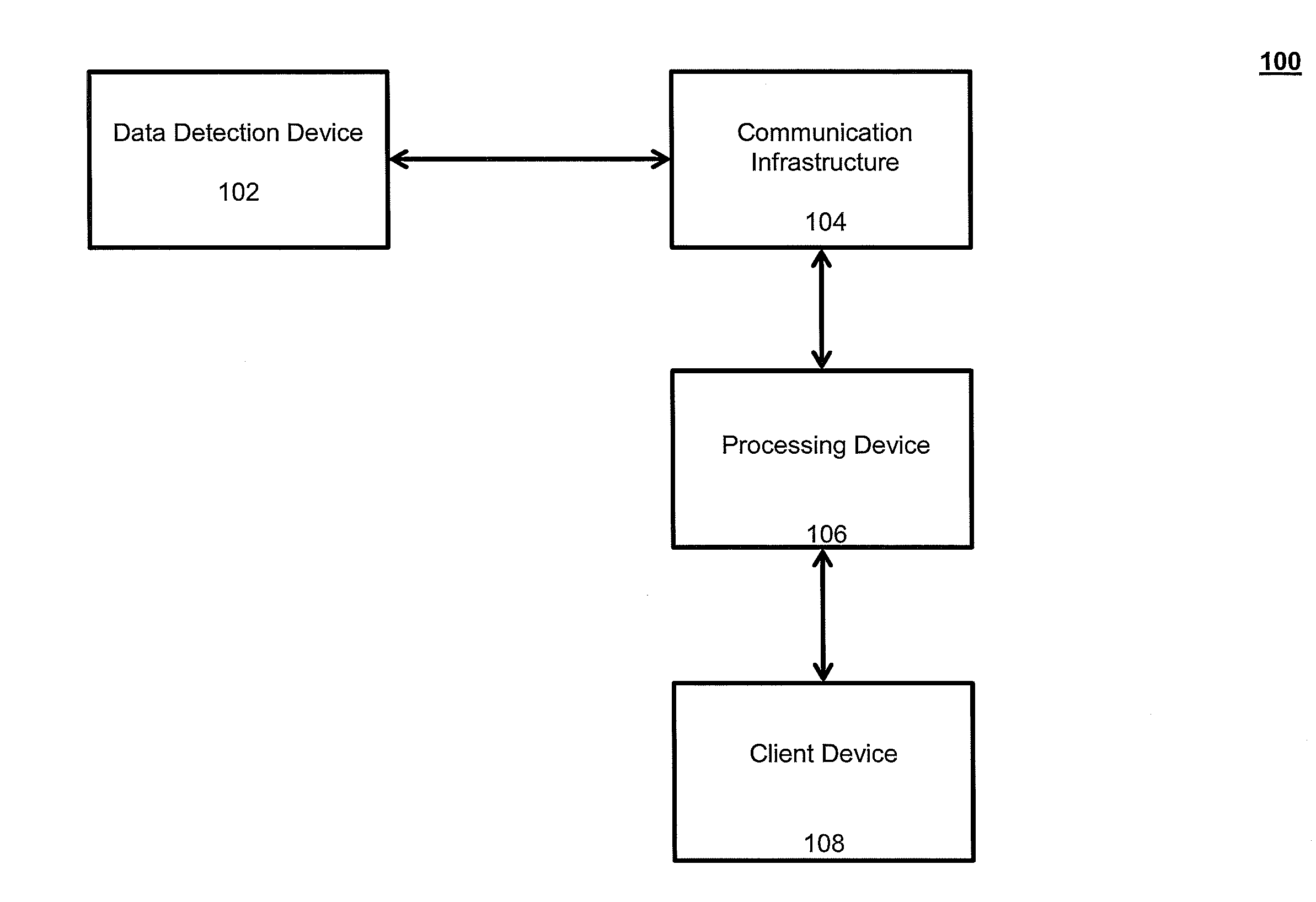
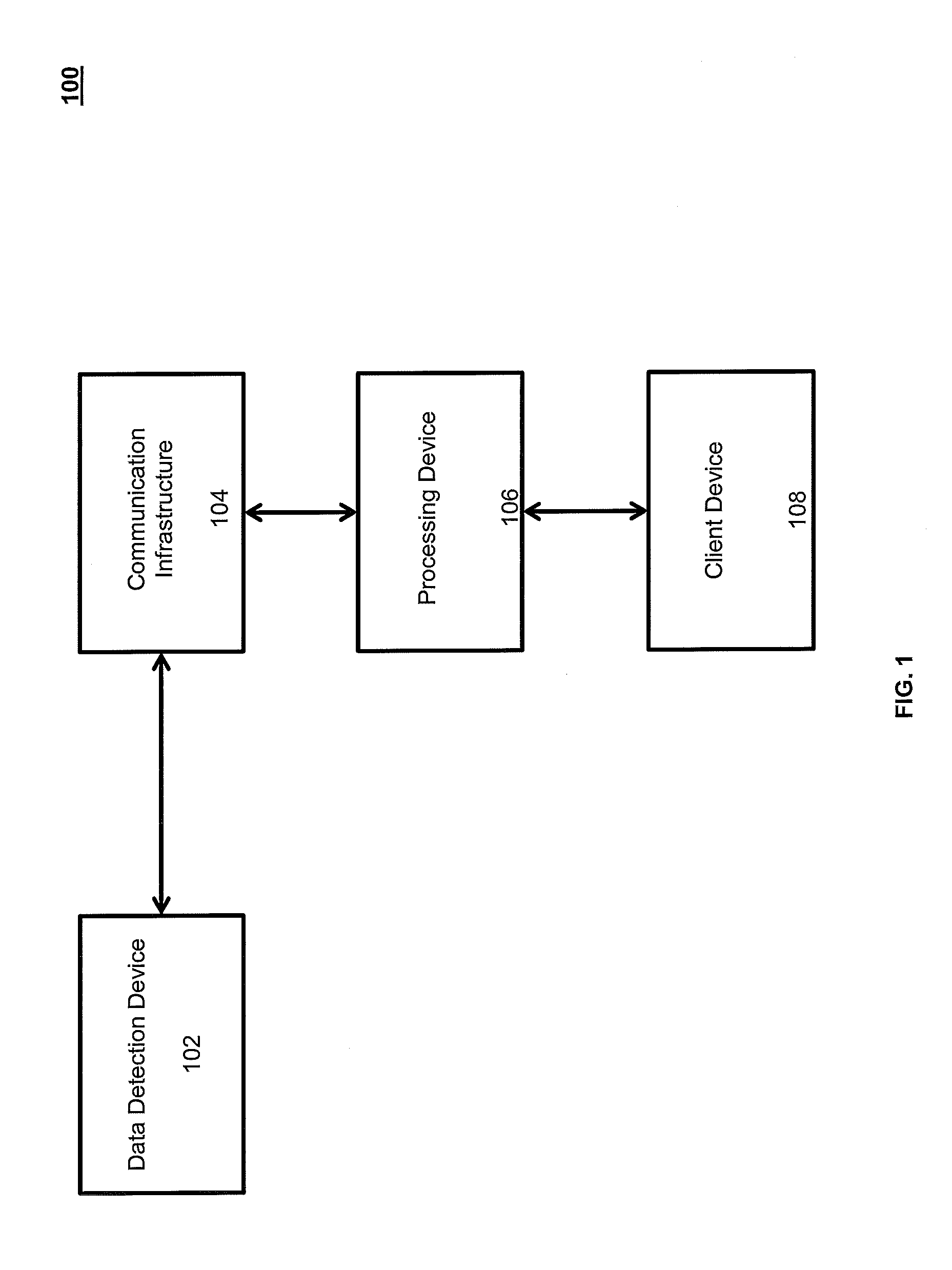
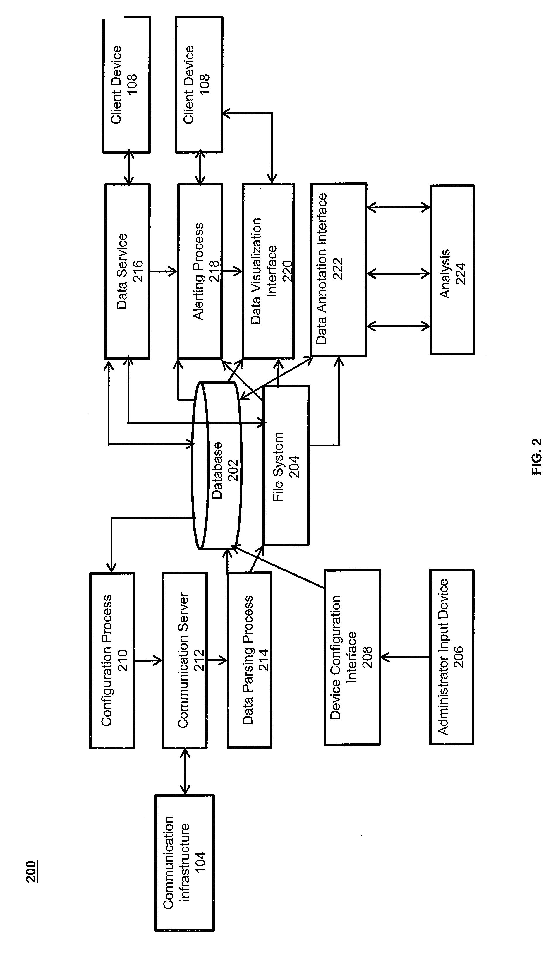
The invention is a system and methods that use automated analysis and information transfer components to efficiently transfer data from a data detection device to a client device in a timely manner. The system includes one or more data detection devices that monitor an area for a source and collect and analyze the data. The data can be sent to one or more destinations in real-time or as needed through a communication infrastructure that includes multiple communication links. The processing device can process and analyze the data and send it to various destinations, such as a client computer or a smartphone. The system can be used in various applications, such as detection of endangered species, remote firearm / poaching detection, and other supervisory control and data acquisition (SCADA) type applications.

Problems solved by technology

However, conventional systems for detecting and analyzing signals, and then transmitting data or information about such data to the one or more destinations are often problematic.
For example, such conventional systems often do not have the necessary communication infrastructure to achieve a seamless transfer of data or information from the collection location to the one or more destinations.
Also, conventional collection systems often cannot process the data according to specific parameters and provide that data or information to a user in a timely manner.
This type of processing of data can cause delays in the transfer of information to the one or more destinations, which may prevent users from being able to use the information or simply always provide largely outdated information to users.

Method used


Image

  • System and methods for remote monitoring
  • System and methods for remote monitoring
  • System and methods for remote monitoring

Examples


Embodiment Construction

[0024]Although a number of embodiments of the invention will be described in the following, it is understood that these embodiments are presented by way of example only, not limitation. The detailed description of the exemplary embodiments of the invention should not be construed to limit the scope or breadth of the invention.

[0025]The invention relates generally to a remote detection system. Different sources, such as humans, animal species, or objects, acts, phenomena, etc. generating signals may be detected by the system and analyzed to determine information. Moreover, embodiments of the system can be configured to facilitate monitoring different environments and areas. It is envisioned that the present invention may be utilized in aquatic, terrestrial, extraterrestrial, and atmospheric environments. It is understood that the particular detection device may vary depending on the selected environment as is understood by those skilled in the art.

[0026]FIG. 1 illustrates an exemplar...


PUM


Abstract

A system that detects signals and transmits data regarding certain detected signals for further analysis is disclosed. The detected signals may be analyzed to determine whether any of the detected signals correspond to a source. The system may transfer in near-real time data and information regarding the data to one or more client devices. Methods for detecting signals and transmitting data associated with the detected signals are also disclosed.

Description

FIELD OF THE INVENTION[0001]The invention relates generally to a system for the remote monitoring of geographical areas. More specifically, the invention relates to a system that collects and processes data and can provide information to a user about the data collected. In certain embodiments, the system can be used to perform enhanced processing of collected data in near-real-time to identify whether an event has taken place or a state has been established and provide information to a user of that occurrence.BACKGROUND OF THE INVENTION[0002]A variety of systems and methods are known by which information regarding the environment can be collected. Detectors, for example, can identify the presence of a human or an animal, the occurrence of an event, or the state of the environment. Humans, animals, or environmental phenomena can generate sound that can be detected. These sounds or audio signals typically have specific characteristics by which the source of the signal can be detected....

Claims


Application Information

Patent Timeline
IPC IPC(8): G01V1/22G01V1/00
CPCG01V1/22G01V1/001A01M31/002G01V2210/14G01V1/01
Inventor CALUPCA, THOMASCLARK, CHRISTOPHER W.FLADUNG, SAMKEMPF, AMANDAROBBINS, MATTHEWSPAULDING, SPAULDING
Owner CORNELL UNIV CORNELL CENT FOR TECH ENTERPRISE & COMMLIZATION CCTEC
Learn More